
Owner manual

KINO-DH810
Page 27
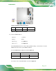
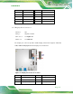
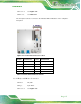
CN Location: See Figure 3-12
CN Pinouts: See Table 3-12
The front panel connector connects to the indicator LEDs and buttons on the computer’s
front panel.
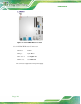
Figure 3-12: Front Panel Connector Location
PIN NO. DESCRIPTION PIN NO. DESCRIPTION
1 NC 2 PWRBTN_SW
3 GND 4 HDDLED+
5 HDDLED- 6 PWRLED+
7 PWRLED+ 8 GND
9 EXTRST- 10 GND
Table 3-12: Front Panel Connector Pinouts
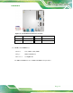
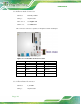
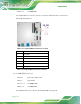
3.2.12 Keyboard/Mouse Connector
CN Label: KB_MS 1
CN Type:
6-pin wafer
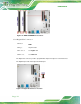
CN Location: See Figure 3-13