
Owner manual

KINO-DH810
Page 24
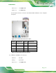
Pin Description Pin Description
7 GND 8 AUX_CTRL_DET_D
9 GND 10 DDI1_HPD#
11 DPD_AUX_CTRL_P2 12 DPD_AUX_CTRL_N2
13 GND 14 DPD_OB_LANE2_P
15 DPD_OB_LANE2_N 16 GND
17 DPD_OB_LANE0_P 18 DPD_OB_LANE0_N
19 +3.3V 20 NC
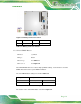
Table 3-8: Display Port Connector Pinouts
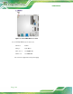
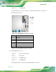
3.2.8 Fan Connector (CPU)
CN Label: CPU_FAN1
CN Type:
4-pin wafer
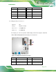
CN Location: See Figure 3-9
CN Pinouts: See Table 3-9
The fan connector attaches to a CPU cooling fan.
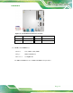
Figure 3-9: CPU Fan Connector Locations
PIN NO. DESCRIPTION PIN NO. DESCRIPTION
1 GND 2 +12V