
Owner manual

KINO-DH810
Page 17
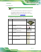
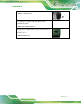
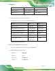
SMBus connector 4-pin wafer CN1
TPM connector 20-pin connector TPM1
USB connectors 8-pin header USB1, USB2
Table 3-1: Peripheral Interface Connectors
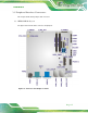
3.1.3 External Interface Panel Connectors
The table below lists the connectors on the external I/O panel.
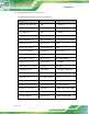
Connector Type Label
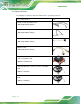
Audio connector Audio jack AUDIO_CV1
Ethernet and USB 3.0 connectors RJ-45, USB 3.0 LAN1_USB1
Ethernet and USB 2.0 connectors RJ-45, USB 2.0 LAN2_USB1
12V DC- IN power connector 4-pin Mini-DIN PWR1
RS-232 serial port connector DB-9 male COM1_2
VGA and DVI connector 15-pin female,
24-pin female
VIDEO1
Table 3-2: Rear Panel Connectors
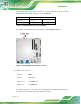
3.2 Internal Peripheral Connectors
The section describes all of the connectors on the KINO-DH810.
3.2.1 AT/ATX Mode Select Switch
CN Label:
J_ATX_AT1
CN Type:
switch
CN Settings:
See Table 3-3
CN Location:
See Figure 3-2