
Manual


KINO-DH610
Page XI
List of Tables
Table 1-1: Technical Specifications..............................................................................................8
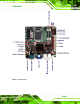
Table 3-1: Peripheral Interface Connectors...............................................................................16
Table 3-2: Rear Panel Connectors ..............................................................................................17
Table 3-3: Battery Connector Pinouts........................................................................................18
Table 3-4: BIOS Update Connector Pinouts ..............................................................................19
Table 3-5: Debug Port Connector Pinouts.................................................................................21
Table 3-6: Digital I/O Connector Pinouts....................................................................................22
Table 3-7: EC Update Connector Pinouts ..................................................................................23
Table 3-8: CPU Fan Connector Pinouts......................................................................................23
Table 3-9: PCH Fan Connector Pinouts......................................................................................24
Table 3-10: Front Panel Connector Pinouts...............................................................................25
Table 3-11: Keyboard/Mouse Connector Pinouts .....................................................................26
Table 3-12: Power Connector Pinouts........................................................................................28
Table 3-13: SATA Power Connector Pinouts.............................................................................30
Table 3-14: RS-232/422/485 Serial Port Connector Pinouts(RS-232+RS422/485) .............31
Table 3-15: TPM Connector Pinouts...........................................................................................32
Table 3-16: USB Connector Pinouts...........................................................................................33
Table 3-17: LAN and USB Connector Pinouts...........................................................................35
Table 3-18: HDMI Connector Pinouts .........................................................................................36
Table 3-19: Power Connector Pinouts........................................................................................37
Table 3-20: RS-232 Serial Port Connector Pinouts ...................................................................37
Table 3-21: DVI and VGA Connector Pinouts ............................................................................38
Table 4-1: Jumpers.......................................................................................................................48
Table 4-2: AT/ATX Mode Select Jumper Settings .....................................................................49
Table 4-3: Clear CMOS Jumper Settings....................................................................................50
Table 5-1: BIOS Navigation Keys................................................................................................62