
Instruction Manual


KINO-CVR-D25502/N26002
Page 44
o When working with the KINO-CVR-D25502/N26002, make sure that it is
disconnected from all power supplies and that no electricity is being fed
into the system.
Before and during the installation of the KINO-CVR-D25502/N26002 DO NOT:
Remove any of the stickers on the PCB board. These stickers are required for
warranty validation.
Use the product before verifying all the cables and power connectors are
properly connected.
Allow screws to come in contact with the PCB circuit, connector pins, or its
components.
4.3 SO-DIMM Ins tallation
To install a SO-DIMM into a SO-DIMM socket, please follow the steps below and refer to
Figure 4-1.
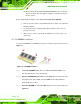
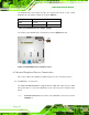
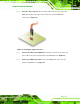
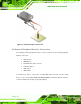
Figure 4-1: SO-DIMM Installation
Step 1: Locate the SO-DIMM socket. Place the KINO-CVR-D25502/N26002 on an
anti-static pad with the solder side facing up.
Step 2: Align the SO-DIMM with the socket. The SO-DIMM must be oriented in such a
way that the notch in the middle of the SO-DIMM must be aligned with the
plastic bridge in the socket.
Step 3: Insert the SO-DIMM. Push the SO-DIMM chip into the socket at an angle. (See
Figure 4-1)