
Instruction Manual


KINO-CVR-D25502/N26002
Page 37
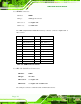
3 DATA0_P 4 GND
5 VCC 6 DATA1_N
7 DATA1_P 8 GND
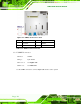
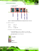
Table 3-19: LAN1_USB1 Connector Pinouts
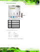
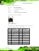
The USB 3.0 ports are for attaching USB 3.0 peripheral devices to the system. To be able
to use the USB 3.0 ports, please make sure the USB 3.0 function is enabled in BIOS (see
Section 5.3.5). The pinouts of LAN2 and USB 3.0 connectors are shown below.
PIN NO. DESCRIPTION PIN NO. DESCRIPTION
P1 1_9VLAN3 P2 LAN1_MDI0+
P3 LAN1_MDI0- P4 LAN1_MDI1+
P5 LAN1_MDI1- P6 LAN1_MDI2+
P7 LAN1_MDI2- P8 LAN1_MDI3+
P9 LAN1_MDI3- P10 GND
L1 L1 L2 L2
L3 L3 L4 L4
P15 GND P16 GND
9 GND 10 GND
11 GND 12 GND
13 GND 14 GND
15 GND 16 GND
U1 VCC U2 USB2.0A-
U3 USB2.0A+ U4 GND
U5 USB3.0ARX- U6 USB3.0ARX+
U7 GND U8 USB3.0ATX-
U9 USB3.0ATX+ U10 VCC
U11 USB2.0A- U12 USB2.0A+
U13 GND U14 USB3.0ARX-
U15 USB3.0ARX+ U16 GND
U17 USB3.0ATX- U18 USB3.0ATX+
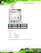
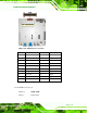
Table 3-20: LAN/USB2 Connector Pinouts