
Instruction Manual


KINO-CVR-D25502/N26002
Page 18
CN Pinouts:
See Table 3-4
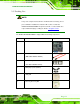
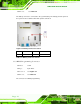
The battery connector is connected to the system battery. The battery provides power to
the system clock to retain the time when power is turned off.
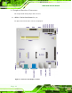
Figure 3-3: Battery Connector Location
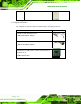
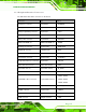
PIN NO. DESCRIPTION PIN NO. DESCRIPTION
1 BAT 2 GND
Table 3-4: Battery Connector Pinouts
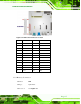
3.2.3 BIOS Programming Connector
CN Label: J SPI1
CN Type:
6-pin wafer
CN Location: See Figure 3-4
CN Pinouts: See Table 3-5
The connector is for BIOS programming.