
User guide


KINO-CV-D25501/N26001 SBC
Page 64
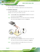
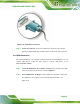
Figure 4-14: LAN Connection
Step 3: Insert the LAN cable RJ-45 connector. Once aligned, gently insert the LAN
cable RJ-45 connector into the on-board RJ-45 connector. Step 0:
4.8.4 Serial Device Connection
The KINO-CV-D25501/N26001 has two single male D-sub 9 connectors on the external
peripheral interface panel for a serial device. Follow the steps below to connect a serial
device to the KINO-CV-D25501/N26001.
Step 1: Locate the D-sub 9 connector. The location of the D-sub 9 connector is shown
in Chapter 3.
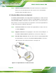
Step 2: Insert the serial connector. Insert the D-sub 9 connector of a serial device into
the D-sub 9 connector on the external peripheral interface. See
Figure 4-15.