
Manual


KINO-AH612
Page 49
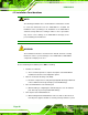
Load Failsafe Defaults.
After having done one of the above, save the changes and exit the CMOS Setup menu.
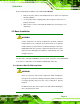
The clear CMOS jumper settings are shown in
Table 4-3.
Setting Description
Short 1-2 Normal Operation Default
Short 2-3 Clear CMOS Setup
Table 4-3: Clear CMOS Jumper Settings
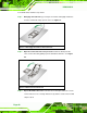
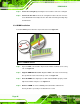
The location of the clear CMOS jumper is shown in Figure 4-10.
Figure 4-10: Clear CMOS Jumper Location
4.5 Internal Peripheral Device Connections
This section outlines the installation of peripheral devices to the on-board connectors
4.5.1 SATA Drive Connection
The KINO-AH612 is shipped with two SATA drive cables. To connect the SATA drives to
the connectors, please follow the steps below.
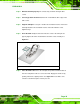
Step 1: Locate the connectors. The locations of the SATA drive connectors are shown
in Chapter 3.
Step 2: Insert the cable connector. Insert the cable connector into the on-board SATA
drive connector until it clips into place. See
Figure 4-11.