
Owner's manual

KINO-AH611
Page 27
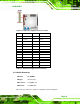
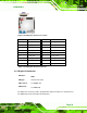
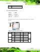
PIN NO. DESCRIPTION
3 GND
Table 3-11: System Fan Connector Pinouts
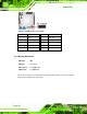
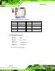
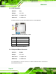
3.2.11 Front Panel Connector
CN Label: F_PANEL
CN Type:
14-pin header
CN Location:
See Figure 3-13
CN Pinou
ts:
See Table 3-12
The front pan
el connector connects to the indicator LEDs and buttons on the computer’s
front panel.
Figure 3-13: Front Panel Connector Location
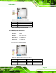
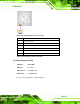
PIN NO. DESCRIPTION PIN NO.
DESCRIPTION
1 ACPILED 2 BEEP_PWR
3 NC 4 NC
PWR_LED
5 GND 6 NC
7 PWRBTN_SW#_C
8 PC_BEEP
BUZZER
PWR_BTN
9 GND 10 NC NC
11 IDELED 12 EXTRST HDD_LED
13 IDELED 14 GND
RESET
Table 3-12: Front Panel Connector Pinouts