
Owner's manual

KINO-AH611
Page 23
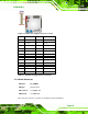
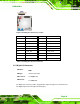
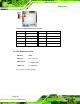
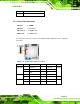
Figure 3-8: Debug Port Connector Location
PIN NO. DESCRIPTION PIN NO. DESCRIPTION
1
EC_EPP_STB#
2 EC_EPP_AFD#
3 EC_EPP_PD0 4 EC_EPP_ERR#
5 EC_EPP_PD1 6 EC_EPP_INIT#
7 EC_EPP_PD2 8 EC_EPP_SLIN#
9 EC_EPP_PD3 10 GND
11 EC_EPP_PD4 12 EC_EPP_ACK#
13 EC_EPP_PD5 14 EC_EPP_BUSY
15 EC_EPP_PD6 16 EC_EPP_PE
17 EC_EPP_PD7 18 EC_EPP_SLCT
Table 3-7: Debug Port Connector Pinouts
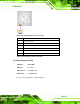
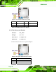
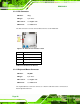
3.2.7 Digital I/O Connector
CN Label:
DIO1
CN Type:
10-pin header (2x5)
CN Location:
See Figure 3-9
CN Pinou
ts:
See Table 3-8
The digital I/O con
nector provides programmable input and output for external devices.
The digital I/O provides 4-bit output and 4-bit input.