
Owner's manual


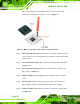

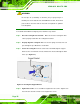

Table Of Contents
- KINO-9652 Mini-ITX SBC
- 1 Introduction
- 2 Detailed Specifications
- 2.1 Overview
- 2.2 Dimensions
- 2.3 Data Flow
- 2.4 Compatible Processors
- 2.5 Intel® GME965 Graphics and Memory Controller Hub
- 2.6 Intel® ICH8ME I/O Controller Hub
- 2.6.1 Intel® ICH8ME Overview
- 2.6.2 Intel® ICH8ME HD Audio Controller
- 2.6.3 Intel® ICH8ME Ethernet Controller
- 2.6.4 Intel® ICH8ME IDE Interface
- 2.6.5 Intel® ICH8ME Low Pin Count (LPC) Interface
- 2.6.6 Intel® ICH8ME PCI Interface
- 2.6.7 Intel® ICH8ME PCIe x1 Bus
- 2.6.8 Intel® ICH8ME Real Time Clock
- 2.6.9 Intel® ICH8ME SATA Controller
- 2.6.10 Intel® ICH8ME Serial Peripheral Interface (SPI) BIOS
- 2.6.11 Intel® ICH8ME USB Controller
- 2.7 PCIe Bus Components
- 2.8 LPC Bus Components
- 2.9 Environmental and Power Specifications
- 3 Unpacking
- 4 Connectors and Jumpers
- 4.1 Peripheral Interface Connectors
- 4.2 Internal Peripheral Connectors
- 4.2.1 Audio Connector
- 4.2.2 Audio CD In Connector
- 4.2.3 ATX Power Connector
- 4.2.4 CompactFlash® Socket (Optional)
- 4.2.5 Fan Connectors
- 4.2.6 Front Panel Connector
- 4.2.7 Digital Input/Output Connector
- 4.2.8 IDE Connector
- 4.2.9 Infrared Interface Connector
- 4.2.10 LCD Backlight Connector
- 4.2.11 LVDS LCD connector
- 4.2.12 SATA Drive Connectors
- 4.2.13 Serial Port Connector
- 4.2.14 Trusted Platform Module (TPM) Connector
- 4.2.15 TV Out Connector
- 4.2.16 Internal USB Connectors
- 4.2.17 On-board LED Indicator
- 4.3 External Interface Connectors
- 5 Installation
- 6 AMI BIOS
- 6.1 Introduction
- 6.2 Main
- 6.3 Advanced
- 6.4 PCI/PnP
- 6.5 Boot
- 6.6 Security
- 6.7 Chipset
- 6.8 Exit
- 7 Software Drivers
- 7.1 Available Software Drivers
- 7.2 Driver CD Auto-run
- 7.3 Intel® Chipset Driver
- 7.4 Intel® Graphics Media Accelerator Driver
- 7.5 Intel® 82566 Gigabit LAN Connect Device Driver
- 7.6 Intel® 82573 PCI Express Gigabit Ethernet Controller Driver
- 7.7 Realtek HD Audio Driver (ALC883) Installation
- 7.8 Intel® Matrix Storage Manager Driver Installation
- 7.9 Intel® Active Management Technology Driver Installation
- 8 Intel® AMT Configuration
- A BIOS Configuration Options
- B Terminology
- C DIO Interface
- D Watchdog Timer
- E Address Mapping
- F Compatibility
- G Hazardous Materials Disclosure
- H External AC’97 Audio CODEC
- I Index
KINO-9652 Mini-ITX SBC
Page 74
CPU socket should be in the unlocked position. If it is not in the unlocked
position, use a screwdriver to unlock the screw. See
Figure 5-1.
Figure 5-1: Make sure the CPU socket retention screw is unlocked
Step 2: Inspect the CPU socket. Make sure there are no bent pins and make sure the
socket contacts are free of foreign material. If any debris is found, remove it with
compressed air.
Step 3: Correctly Orientate the CPU. Make sure the IHS (integrated heat sink) side is
facing upwards.
Step 4: Correctly position the CPU. Match the Pin 1 mark with the cut edge on the
CPU socket. See
Figure 5-1.
Step 5: Align the CPU pins. Carefully align the CPU pins with the holes in the CPU
socket.
Step 6: Insert the CPU. Gently insert the CPU into the socket. If the CPU pins are
properly aligned, the CPU should slide into the CPU socket smoothly.
Step 7: Lock the retention screw. Rotate the retention screw into the locked position.
See
Figure 5-2.Step 0: