
Owner's manual
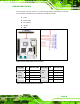
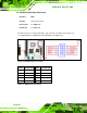


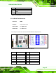
Table Of Contents
- KINO-9652 Mini-ITX SBC
- 1 Introduction
- 2 Detailed Specifications
- 2.1 Overview
- 2.2 Dimensions
- 2.3 Data Flow
- 2.4 Compatible Processors
- 2.5 Intel® GME965 Graphics and Memory Controller Hub
- 2.6 Intel® ICH8ME I/O Controller Hub
- 2.6.1 Intel® ICH8ME Overview
- 2.6.2 Intel® ICH8ME HD Audio Controller
- 2.6.3 Intel® ICH8ME Ethernet Controller
- 2.6.4 Intel® ICH8ME IDE Interface
- 2.6.5 Intel® ICH8ME Low Pin Count (LPC) Interface
- 2.6.6 Intel® ICH8ME PCI Interface
- 2.6.7 Intel® ICH8ME PCIe x1 Bus
- 2.6.8 Intel® ICH8ME Real Time Clock
- 2.6.9 Intel® ICH8ME SATA Controller
- 2.6.10 Intel® ICH8ME Serial Peripheral Interface (SPI) BIOS
- 2.6.11 Intel® ICH8ME USB Controller
- 2.7 PCIe Bus Components
- 2.8 LPC Bus Components
- 2.9 Environmental and Power Specifications
- 3 Unpacking
- 4 Connectors and Jumpers
- 4.1 Peripheral Interface Connectors
- 4.2 Internal Peripheral Connectors
- 4.2.1 Audio Connector
- 4.2.2 Audio CD In Connector
- 4.2.3 ATX Power Connector
- 4.2.4 CompactFlash® Socket (Optional)
- 4.2.5 Fan Connectors
- 4.2.6 Front Panel Connector
- 4.2.7 Digital Input/Output Connector
- 4.2.8 IDE Connector
- 4.2.9 Infrared Interface Connector
- 4.2.10 LCD Backlight Connector
- 4.2.11 LVDS LCD connector
- 4.2.12 SATA Drive Connectors
- 4.2.13 Serial Port Connector
- 4.2.14 Trusted Platform Module (TPM) Connector
- 4.2.15 TV Out Connector
- 4.2.16 Internal USB Connectors
- 4.2.17 On-board LED Indicator
- 4.3 External Interface Connectors
- 5 Installation
- 6 AMI BIOS
- 6.1 Introduction
- 6.2 Main
- 6.3 Advanced
- 6.4 PCI/PnP
- 6.5 Boot
- 6.6 Security
- 6.7 Chipset
- 6.8 Exit
- 7 Software Drivers
- 7.1 Available Software Drivers
- 7.2 Driver CD Auto-run
- 7.3 Intel® Chipset Driver
- 7.4 Intel® Graphics Media Accelerator Driver
- 7.5 Intel® 82566 Gigabit LAN Connect Device Driver
- 7.6 Intel® 82573 PCI Express Gigabit Ethernet Controller Driver
- 7.7 Realtek HD Audio Driver (ALC883) Installation
- 7.8 Intel® Matrix Storage Manager Driver Installation
- 7.9 Intel® Active Management Technology Driver Installation
- 8 Intel® AMT Configuration
- A BIOS Configuration Options
- B Terminology
- C DIO Interface
- D Watchdog Timer
- E Address Mapping
- F Compatibility
- G Hazardous Materials Disclosure
- H External AC’97 Audio CODEC
- I Index
KINO-9652 Mini-ITX SBC
Page 52
PIN NO. DESCRIPTION PIN NO. DESCRIPTION
1 RESET# 2 GND
3 DATA 7 4 DATA 8
5 DATA 6 6 DATA 9
7 DATA 5 8 DATA 10
9 DATA 4 10 DATA 11
11 DATA 3 12 DATA 12
13 DATA 2 14 DATA 13
15 DATA 1 16 DATA 14
17 DATA 0 18 DATA 15
19 GND 20 N/C
21 IDE DRQ 22 GND
23 IOW# 24 GND
25 IOR# 26 GND
27 IDE CHRDY 28 BALE – DEFAULT
29 IDE DACK 30 GND
31 INTERRUPT 32 N/C
33 SA1 34 PDIAG#
35 SA0 36 SA2
37 HDC CS0# 38 HDC CS1#
39 HDD ACTIVE# 40 GND
Table 4-10: IDE Connector Pinouts
4.2.9 Infrared Interface Connector
CN Label: IR1
CN Type:
5-pin header (1x5)
CN Location: See
Figure 4-10
CN Pinouts:
See
Table 4-11
The infrared interface connector supports both Serial Infrared (SIR) and Amplitude Shift
Key Infrared (ASKIR) interfaces.