
Owner's manual


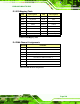


Table Of Contents
- KINO-9652 Mini-ITX SBC
- 1 Introduction
- 2 Detailed Specifications
- 2.1 Overview
- 2.2 Dimensions
- 2.3 Data Flow
- 2.4 Compatible Processors
- 2.5 Intel® GME965 Graphics and Memory Controller Hub
- 2.6 Intel® ICH8ME I/O Controller Hub
- 2.6.1 Intel® ICH8ME Overview
- 2.6.2 Intel® ICH8ME HD Audio Controller
- 2.6.3 Intel® ICH8ME Ethernet Controller
- 2.6.4 Intel® ICH8ME IDE Interface
- 2.6.5 Intel® ICH8ME Low Pin Count (LPC) Interface
- 2.6.6 Intel® ICH8ME PCI Interface
- 2.6.7 Intel® ICH8ME PCIe x1 Bus
- 2.6.8 Intel® ICH8ME Real Time Clock
- 2.6.9 Intel® ICH8ME SATA Controller
- 2.6.10 Intel® ICH8ME Serial Peripheral Interface (SPI) BIOS
- 2.6.11 Intel® ICH8ME USB Controller
- 2.7 PCIe Bus Components
- 2.8 LPC Bus Components
- 2.9 Environmental and Power Specifications
- 3 Unpacking
- 4 Connectors and Jumpers
- 4.1 Peripheral Interface Connectors
- 4.2 Internal Peripheral Connectors
- 4.2.1 Audio Connector
- 4.2.2 Audio CD In Connector
- 4.2.3 ATX Power Connector
- 4.2.4 CompactFlash® Socket (Optional)
- 4.2.5 Fan Connectors
- 4.2.6 Front Panel Connector
- 4.2.7 Digital Input/Output Connector
- 4.2.8 IDE Connector
- 4.2.9 Infrared Interface Connector
- 4.2.10 LCD Backlight Connector
- 4.2.11 LVDS LCD connector
- 4.2.12 SATA Drive Connectors
- 4.2.13 Serial Port Connector
- 4.2.14 Trusted Platform Module (TPM) Connector
- 4.2.15 TV Out Connector
- 4.2.16 Internal USB Connectors
- 4.2.17 On-board LED Indicator
- 4.3 External Interface Connectors
- 5 Installation
- 6 AMI BIOS
- 6.1 Introduction
- 6.2 Main
- 6.3 Advanced
- 6.4 PCI/PnP
- 6.5 Boot
- 6.6 Security
- 6.7 Chipset
- 6.8 Exit
- 7 Software Drivers
- 7.1 Available Software Drivers
- 7.2 Driver CD Auto-run
- 7.3 Intel® Chipset Driver
- 7.4 Intel® Graphics Media Accelerator Driver
- 7.5 Intel® 82566 Gigabit LAN Connect Device Driver
- 7.6 Intel® 82573 PCI Express Gigabit Ethernet Controller Driver
- 7.7 Realtek HD Audio Driver (ALC883) Installation
- 7.8 Intel® Matrix Storage Manager Driver Installation
- 7.9 Intel® Active Management Technology Driver Installation
- 8 Intel® AMT Configuration
- A BIOS Configuration Options
- B Terminology
- C DIO Interface
- D Watchdog Timer
- E Address Mapping
- F Compatibility
- G Hazardous Materials Disclosure
- H External AC’97 Audio CODEC
- I Index
KINO-9652 Mini-ITX SBC
Page 219
NOTE:
The following discussion applies to DOS environment. IEI support is
contacted or the IEI website visited for specific drivers for more
sophisticated operating systems, e.g., Windows and Linux.
The Watchdog Timer is provided to ensure that standalone systems can always recover
from catastrophic conditions that cause the CPU to crash. This condition may have
occurred by external EMI or a software bug. When the CPU stops working correctly,
Watchdog Timer either performs a hardware reset (cold boot) or a Non-Maskable Interrupt
(NMI) to bring the system back to a known state.
A BIOS function call (INT 15H) is used to control the Watchdog Timer:
INT 15H:
AH – 6FH Sub-function:
AL – 2: Sets the Watchdog Timer’s period.
BL: Time-out value (Its unit-second is dependent on the item “Watchdog
Timer unit select” in CMOS setup).
Table D-1: AH-6FH Sub-function
Call sub-function 2 to set the time-out period of Watchdog Timer first. If the time-out value
is not zero, the Watchdog Timer starts counting down. While the timer value reaches zero,
the system resets. To ensure that this reset condition does not occur, calling sub-function
2 must periodically refresh the Watchdog Timer. However, the Watchdog timer is disabled
if the time-out value is set to zero.
A tolerance of at least 10% must be maintained to avoid unknown routines within the
operating system (DOS), such as disk I/O that can be very time-consuming.