
Owner's manual
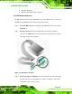


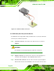

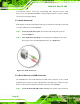
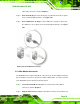


Table Of Contents
- KINO-9652 Mini-ITX SBC
- 1 Introduction
- 2 Detailed Specifications
- 2.1 Overview
- 2.2 Dimensions
- 2.3 Data Flow
- 2.4 Compatible Processors
- 2.5 Intel® GME965 Graphics and Memory Controller Hub
- 2.6 Intel® ICH8ME I/O Controller Hub
- 2.6.1 Intel® ICH8ME Overview
- 2.6.2 Intel® ICH8ME HD Audio Controller
- 2.6.3 Intel® ICH8ME Ethernet Controller
- 2.6.4 Intel® ICH8ME IDE Interface
- 2.6.5 Intel® ICH8ME Low Pin Count (LPC) Interface
- 2.6.6 Intel® ICH8ME PCI Interface
- 2.6.7 Intel® ICH8ME PCIe x1 Bus
- 2.6.8 Intel® ICH8ME Real Time Clock
- 2.6.9 Intel® ICH8ME SATA Controller
- 2.6.10 Intel® ICH8ME Serial Peripheral Interface (SPI) BIOS
- 2.6.11 Intel® ICH8ME USB Controller
- 2.7 PCIe Bus Components
- 2.8 LPC Bus Components
- 2.9 Environmental and Power Specifications
- 3 Unpacking
- 4 Connectors and Jumpers
- 4.1 Peripheral Interface Connectors
- 4.2 Internal Peripheral Connectors
- 4.2.1 Audio Connector
- 4.2.2 Audio CD In Connector
- 4.2.3 ATX Power Connector
- 4.2.4 CompactFlash® Socket (Optional)
- 4.2.5 Fan Connectors
- 4.2.6 Front Panel Connector
- 4.2.7 Digital Input/Output Connector
- 4.2.8 IDE Connector
- 4.2.9 Infrared Interface Connector
- 4.2.10 LCD Backlight Connector
- 4.2.11 LVDS LCD connector
- 4.2.12 SATA Drive Connectors
- 4.2.13 Serial Port Connector
- 4.2.14 Trusted Platform Module (TPM) Connector
- 4.2.15 TV Out Connector
- 4.2.16 Internal USB Connectors
- 4.2.17 On-board LED Indicator
- 4.3 External Interface Connectors
- 5 Installation
- 6 AMI BIOS
- 6.1 Introduction
- 6.2 Main
- 6.3 Advanced
- 6.4 PCI/PnP
- 6.5 Boot
- 6.6 Security
- 6.7 Chipset
- 6.8 Exit
- 7 Software Drivers
- 7.1 Available Software Drivers
- 7.2 Driver CD Auto-run
- 7.3 Intel® Chipset Driver
- 7.4 Intel® Graphics Media Accelerator Driver
- 7.5 Intel® 82566 Gigabit LAN Connect Device Driver
- 7.6 Intel® 82573 PCI Express Gigabit Ethernet Controller Driver
- 7.7 Realtek HD Audio Driver (ALC883) Installation
- 7.8 Intel® Matrix Storage Manager Driver Installation
- 7.9 Intel® Active Management Technology Driver Installation
- 8 Intel® AMT Configuration
- A BIOS Configuration Options
- B Terminology
- C DIO Interface
- D Watchdog Timer
- E Address Mapping
- F Compatibility
- G Hazardous Materials Disclosure
- H External AC’97 Audio CODEC
- I Index
KINO-9652 Mini-ITX SBC
Page 90
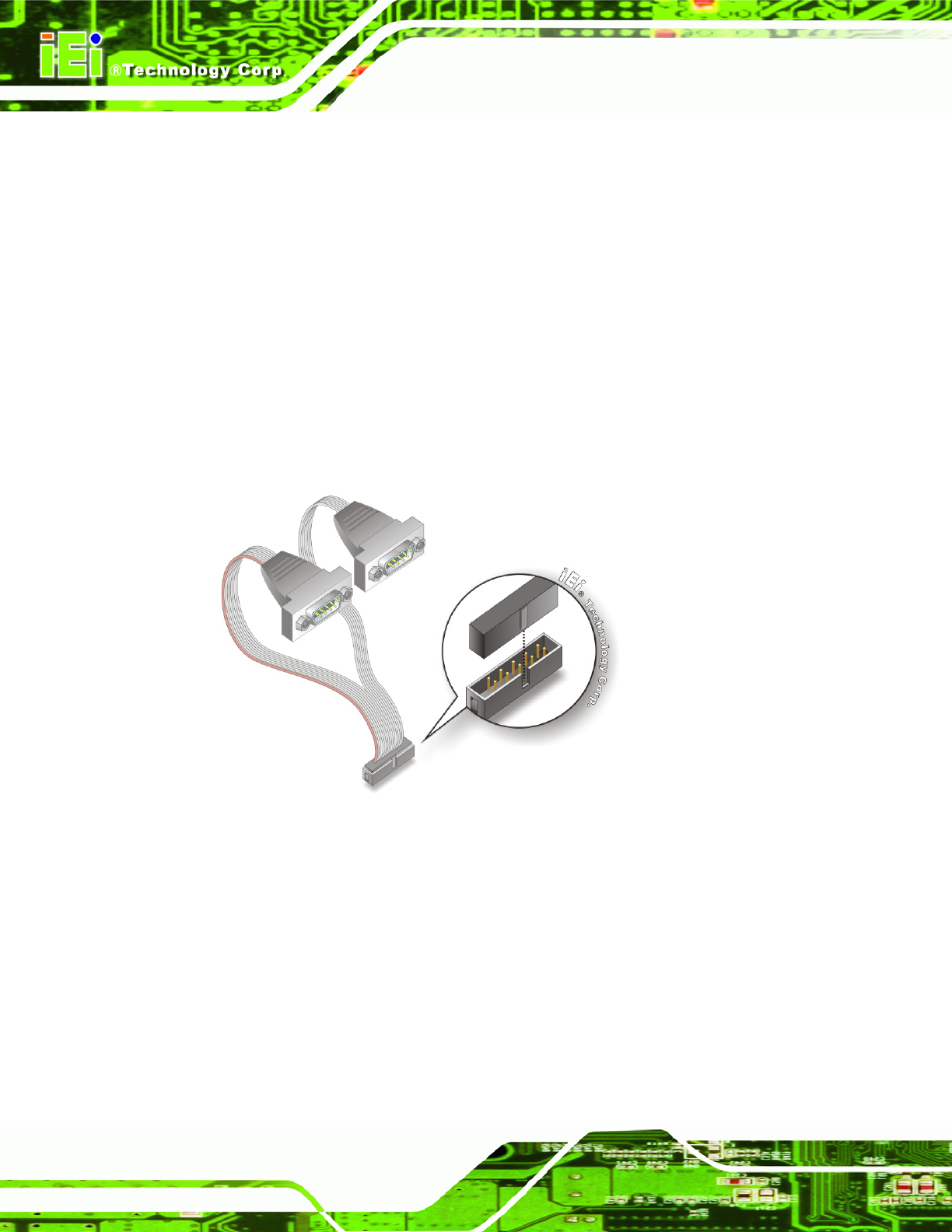
5.6.3 Dual RS-232 Cable Connection
The dual RS-232 cable consists of two connectors attached to two independent cables.
Each cable is then attached to a D-sub 9-pin male connector. To install the dual RS-232
cable, please follow the steps below.
Step 1: Locate the connectors. The locations of the RS-232 connectors are shown in
Chapter 3.
Step 2: Insert the cable connectors. Insert one connector into each serial port box
headers. See
Figure 5-15. A key on the front of the cable connectors ensures
the connector can only be installed in one direction.
Figure 5-15: Dual RS-232 Cable Installation
Step 3: Secure the connectors. Both single RS-232 connectors have two retention
screws that must be secured to a chassis or bracket.
Step 4: Connect the serial device. Once the single RS-232 connectors are connected
to a chassis or bracket, a serial communications device can be connected to the
system. Step 0: