
Owner's manual


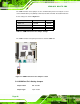


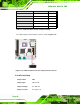

Table Of Contents
- KINO-9652 Mini-ITX SBC
- 1 Introduction
- 2 Detailed Specifications
- 2.1 Overview
- 2.2 Dimensions
- 2.3 Data Flow
- 2.4 Compatible Processors
- 2.5 Intel® GME965 Graphics and Memory Controller Hub
- 2.6 Intel® ICH8ME I/O Controller Hub
- 2.6.1 Intel® ICH8ME Overview
- 2.6.2 Intel® ICH8ME HD Audio Controller
- 2.6.3 Intel® ICH8ME Ethernet Controller
- 2.6.4 Intel® ICH8ME IDE Interface
- 2.6.5 Intel® ICH8ME Low Pin Count (LPC) Interface
- 2.6.6 Intel® ICH8ME PCI Interface
- 2.6.7 Intel® ICH8ME PCIe x1 Bus
- 2.6.8 Intel® ICH8ME Real Time Clock
- 2.6.9 Intel® ICH8ME SATA Controller
- 2.6.10 Intel® ICH8ME Serial Peripheral Interface (SPI) BIOS
- 2.6.11 Intel® ICH8ME USB Controller
- 2.7 PCIe Bus Components
- 2.8 LPC Bus Components
- 2.9 Environmental and Power Specifications
- 3 Unpacking
- 4 Connectors and Jumpers
- 4.1 Peripheral Interface Connectors
- 4.2 Internal Peripheral Connectors
- 4.2.1 Audio Connector
- 4.2.2 Audio CD In Connector
- 4.2.3 ATX Power Connector
- 4.2.4 CompactFlash® Socket (Optional)
- 4.2.5 Fan Connectors
- 4.2.6 Front Panel Connector
- 4.2.7 Digital Input/Output Connector
- 4.2.8 IDE Connector
- 4.2.9 Infrared Interface Connector
- 4.2.10 LCD Backlight Connector
- 4.2.11 LVDS LCD connector
- 4.2.12 SATA Drive Connectors
- 4.2.13 Serial Port Connector
- 4.2.14 Trusted Platform Module (TPM) Connector
- 4.2.15 TV Out Connector
- 4.2.16 Internal USB Connectors
- 4.2.17 On-board LED Indicator
- 4.3 External Interface Connectors
- 5 Installation
- 6 AMI BIOS
- 6.1 Introduction
- 6.2 Main
- 6.3 Advanced
- 6.4 PCI/PnP
- 6.5 Boot
- 6.6 Security
- 6.7 Chipset
- 6.8 Exit
- 7 Software Drivers
- 7.1 Available Software Drivers
- 7.2 Driver CD Auto-run
- 7.3 Intel® Chipset Driver
- 7.4 Intel® Graphics Media Accelerator Driver
- 7.5 Intel® 82566 Gigabit LAN Connect Device Driver
- 7.6 Intel® 82573 PCI Express Gigabit Ethernet Controller Driver
- 7.7 Realtek HD Audio Driver (ALC883) Installation
- 7.8 Intel® Matrix Storage Manager Driver Installation
- 7.9 Intel® Active Management Technology Driver Installation
- 8 Intel® AMT Configuration
- A BIOS Configuration Options
- B Terminology
- C DIO Interface
- D Watchdog Timer
- E Address Mapping
- F Compatibility
- G Hazardous Materials Disclosure
- H External AC’97 Audio CODEC
- I Index

KINO-9652 Mini-ITX SBC
Page 80
Description Label Type
Clear CMOS J_CMOS1 3-pin header
COM 4 function selection JP5 6-pn header
COM port RI and voltage selection JP1, JP2 10-pin header
LVDS LCD voltage selection J_VLVDS1 3-pin header
LVDS LCD resolution selection JP3 8-pin header
CF card setup (optional) JCF1 2-pin header
Table 5-1: Jumpers
5.4.1 Clear CMOS Jumper
Jumper Label: J_COMS1
Jumper Type:
3-pin header
Jumper Settings: See
Table 5-2
Jumper Location: See
Figure 5-8
If the KINO-9652 fails to boot due to improper BIOS settings, the clear CMOS jumper
clears the CMOS data and resets the system BIOS information. To do this, use the jumper
cap to close pins 2 and 3 for a few seconds then reinstall the jumper clip back to pins 1
and 2.
If the “CMOS Settings Wrong” message is displayed during the boot up process, the fault
may be corrected by pressing the F1 to enter the CMOS Setup menu. Do one of the
following:
Enter the correct CMOS setting
Load Optimal Defaults
Load Failsafe Defaults.
After having done one of the above, save the changes and exit the CMOS Setup menu.