
Manual


KINO-9652 Mini-ITX SBC
Page 45
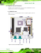
CN Location: See Figure 4-4
CN Pinouts: See
Table 4-5
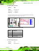
The ATX connector is connected to an external ATX power supply. Power is provided to
the system, from the power supply through this connector.
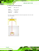
Figure 4-4: ATX Power Connector Pinout Locations
PIN NO. DESCRIPTION PIN NO. DESCRIPTION
1 +3.3V 11 +3.3V
2 +3.3V 12 -12V
3 GND 13 GND
4 +5V 14 PS-ON
5 GND 15 GND
6 +5V 16 GND
7 GND 17 GND
8 PW-OK 18 -5V
9 +VCC5SB 19 +5V
10 +12V 20 +5V
Table 4-5: ATX Power Connector Pinouts