
Manual


KINO-9652 Mini-ITX SBC
Page 83
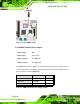
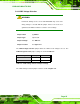
The COM 4 Function Select jumper location is shown in Table 5-3.
Figure 5-9: COM 4 Function Select Jumper Location
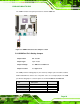
5.4.3 COM Port Pin 9 Setting Jumpers
Jumper Label: JP1 and JP2
Jumper Type:
10-pin header
Jumper Settings: See
Table 5-4 and Table 5-5
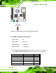
Jumper Location: See
Figure 5-10
The COM port Pin 9 Setting jumpers (JP1 and JP2) configure pin 9 on COM 1, COM 2,
COM 3 and COM 4 as either a +5V, +12V power source or as a ring-in (RI) line. The COM
port Pin 9 Setting jumpers selection options are shown in
Table 5-4 and Table 5-5.
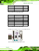
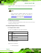
JP1 Description
Short 1 – 3 COM 1 RI Pin use +12V
Short 3 – 5 COM 1 RI Pin use +5V
Short 5 – 7 COM 1 RI Pin use +5V