
Instruction Manual


KINO-945GSE2 Motherboard
Page 41
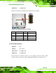
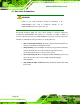
Figure 3-22: USB Connector Pinout Locations
Pin Description Pin Description
1 VCC 2 GND
3 DATA- 4 DATA+
5 DATA+ 6 DATA-
7 GND 8 VCC
Table 3-23: USB Port Connector Pinouts
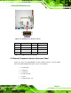
3.3 External Peripheral Interface Connector Panel
6Figure 3-23 shows the KINO-945GSE2 external peripheral interface connector (EPIC)
panel. The KINO-945GSE2 EPIC panel consists of the following:
1 x Power DIN
1 x VGA port
1 x Serial port
4 x USB connectors
1 x RJ-45
1 x Audio jack (line out)