
Instruction Manual

KINO-945GSE2 Motherboard
Page 30
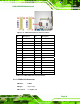
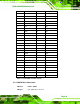
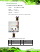
CN Pinouts:
See
Table 3-12
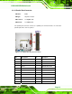
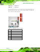
The 30-pin LVDS LCD connector can be connected to single channel or dual channel,
18-bit or 36-bit LVDS panel.
Figure 3-12: LVDS LCD Connector Pinout Locations
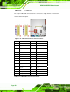
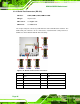
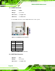
Pin Description Pin Description
1 GND1 2 GND2
3 A_Y0+ 4 A_Y0-
5 A_Y1+ 6 A_Y1-
7 A_Y2+ 8 A_Y2-
9 LVDS_CK1+ 10 LVDS_CK1-
11 A_Y3+ 12 A_Y3-
13 GND3 14 GND4
15 A_Y4+ 16 A_Y4-
17 A_Y5+ 18 A_Y5-
19 A_Y6+ 20 A_Y6-
21 LVDS_CK2+ 22 LVDS_CK2-
23 A_Y7+ 24 A_Y7-
25 GND5 26 GND6
27 VCC_LCD 28 VCC_LCD
29 VCC_LCD 30 VCC_LCD
Table 3-13: LVDS LCD Port Connector Pinouts