
Instruction Manual


KINO-945GSE2 Motherboard
Page 25
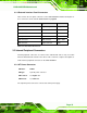
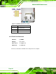
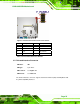
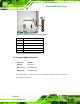
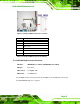
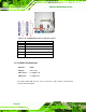
Figure 3-7: Front Panel Connector Pinout Locations
Pin Description Pin Description
1 PWRBTSW- 2 VCC5
3 GND 4 GND
5 VCC5 6 PM_SYSRST#
7 -HDLED 8 GND
Table 3-8: Front Panel Connector Pinouts
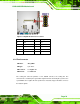
3.2.7 Infrared Interface Connector
CN Label: IR1
CN Type:
5-pin wafer
CN Location:
See
5Figure 3-8
CN Pinouts:
See
6Table 3-9
The infrared interface connector supports both Serial Infrared (SIR) and Amplitude Shift
Key Infrared (ASKIR) interfaces.