
Instruction Manual


KINO-945GSE2 Motherboard
Page 18
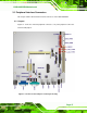
3.1.2 Internal Peripheral Interface Connectors
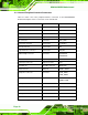
5Table 3-1 shows a list of the peripheral interface connectors on the KINO-945GSE2.
Detailed descriptions of these connectors can be found below.
Connector Type Label
ATX 12 V power connector 4-pin connector PWR2
Audio connector 10-pin header AUDIO1
Battery connector 2-pin box header BT1
Digital I/O connector 10-pin header DIO1
Fan connector 3-pin wafer CPU_FAN1
Front panel connector 8-pin header F_PANEL1
Infrared connector 5-pin header IR1
Keyboard/mouse connector 6-pin header KB_MS1
LCD backlight connector 5-pin wafer INVERTER1,
INVERTER2
LVDS connector 30-pin crimp LVDS1, LVDS2
Parallel port connector 26-pin box header LPT1
PCIe Mini slot PCIe Mini connector MINIPCIE1
SATA connector SATA port SATA1, SATA2
SATA power connector 4-pin wafer SATA_PWR1,
SATA_PWR2
Serial port connector (RS-232) 10-pin header COM2, COM3, COM4,
COM5, COM6
Serial port connector (RS-422/485) 6-pin header JP3, JP5
SPDIF connector 5-pin header SPDIF1
SPI flash connector 8-pin header SPI1
TV output connector 6-pin header TV1
USB connector 8-pin header USB4
Table 3-1: Peripheral Interface Connectors