
User Manual


KINO-945GSE Motherboard
Page 62
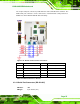
CN Pinouts:
See
7Table 4-22
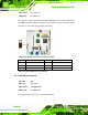
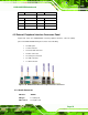
The KINO-945GSE is equipped with two built-in RJ-45 Ethernet controllers. The
controllers can connect to the LAN through two RJ-45 LAN connectors. There are two
LEDs on the connector indicating the status of LAN. The pin assignments are listed in the
following table:
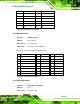
PIN
DESCRIPTION PIN DESCRIPTION
1 MDIA3- 5 MDIA1+
2 MDIA3+ 6 MDIA2+
3 MDIA2- 7 MDIA0-
4 MDIA1- 8 MDIA0+
Table 4-22: LAN Pinouts
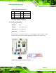
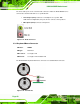
Figure 4-23: RJ-45 Ethernet Connector
The RJ-45 Ethernet connector has two status LEDs, one green and one yellow. The green
LED indicates activity on the port and the yellow LED indicates the port is linked. See
7Table 4-23.
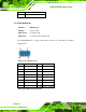
STATUS DESCRIPTION STATUS DESCRIPTION
GREEN Activity YELLOW Linked
Table 4-23: RJ-45 Ethernet Connector LEDs
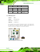
4.3.5 Serial Port Connectors
CN Label: COM1 and COM2
CN Type:
DB-9 connectors
CN Location:
See
Figure 4-20 (see 2)
CN Pinouts:
See
Table 4-24 and Figure 4-24