
User Manual


KINO-945GSE Motherboard
Page 61
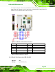
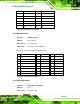
PIN DESCRIPTION PIN DESCRIPTION
1 L_KDAT 7 L_MDAT
2 NC 8 NC
3 GND 9 GND
4 5 V 10 5 V
5 L_KCLK 11 L_MCLK
6 NC 12 NC
Table 4-20: PS/2 Connector Pinouts
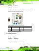
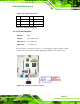
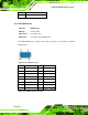
4.3.3 DVI Connector
CN Label: VIDEO1 (bottom)
CN Type:
DVI connector
CN Location:
See
Figure 4-20
CN Pinouts:
See
Figure 4-22 and Table 4-21
Connects to a monitor that supports DVI video input.
PIN
Signal Name
Pin
Signal Name
Pin
Signal Name
1
TMDS Data2-
9
TMDS Data1-
17
TMDS Data0-
2
TMDS Data2+
10
TMDS Data1+
18
TMDS Data0+
3
GND
11
GND
19
GND
4
N/C
12
NC
20
NC
5
N/C
13
NC
21
NC
6
DDC Clock [SCL]
14
PVDD1
22
GND
7
DDC Data [SDA]
15
GND
23
TMDS Clock +
8
Analog vertical sync
16
HPDET
24
TMDS Clock -
Table 4-21: DVI Connector Pinouts
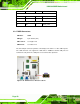
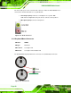
4.3.4 LAN Connectors
CN Label: LAN/USB1 & LAN/USB2
CN Type:
RJ-45
CN Location:
See
7Figure 4-20