
User Manual


KINO-945GSE Motherboard
Page 56
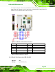
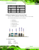
CN Location:
See
Figure 4-16
CN Pinouts:
See
7Table 4-16
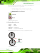
The serial port connector provides the RS-422 and RS-485 pins for serial port COM3. JP1
sets COM3 to RS-232, RS-422 or RS-485, use the COM3 connector for RS-232 and the
connectors on JP2 for RS-422 or RS-485 connectivity.
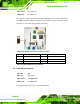
Figure 4-16: RS-422/485 Connector Pinout Locations
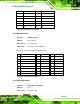
PIN NO. DESCRIPTION PIN NO. DESCRIPTION
1 TX_422- 2 RX3-
3 TX_422+ 4 RX3+
5 Data+ 6 Data-
Table 4-16: RS-422/485 Connector Pinouts
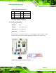
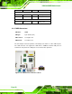
4.2.15 SPI Flash Connector
CN Label: SPI1
CN Type:
6-pin header
CN Location:
See
Figure 4-17
CN Pinouts:
See
Table 4-17
The 6-pin SPI Flash connector is used to flash the BIOS.