
Manual
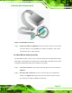
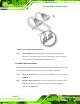
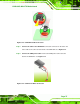

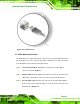
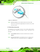
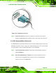
Table Of Contents
- 1 Introduction
- 2 Detailed Specifications
- 3 Unpacking
- 4 Connector Pinouts
- 4.1 Peripheral Interface Connectors
- 4.2 Internal Peripheral Connectors
- 4.2.1 Fan Connectors
- 4.2.2 Front Panel Connector
- 4.2.3 Digital Input/Output Connector
- 4.2.4 IDE Connector
- 4.2.5 LCD Backlight Connector
- 4.2.6 LVDS LCD connector
- 4.2.7 Power Connector
- 4.2.8 14-Pin Serial Port Connectors
- 4.2.9 10-Pin Serial Port Connectors
- 4.2.10 SATA Drive Connectors
- 4.2.11 SPDIF Connector
- 4.2.12 Internal USB Connectors
- 4.3 External Interface Connectors
- 5 Installation
- 6 AMI BIOS
- 7 Driver Installation
- A BIOS Options
- B DIO Interface
- C Watchdog Timer

KINO-9453 Mini-ITX Motherboard
Page 75
Figure 5-14: IDE Cable Connection
Step 3: Connect the cable to an IDE device. Connect the two connectors on the other
side of the cable to one or two IDE devices. Make sure that pin 1 on the cable
corresponds to pin 1 on the connectorStep 0:
5.6.3 Dual RS-232 Cable Connection
The dual RS-232 cable consists of two connectors attached to two independent cables.
Each cable is then attached to a D-sub 9 male connector that is mounted onto a bracket.
To install the dual RS-232 cable, please follow the steps below.
Step 1: Locate the connectors. The locations of the RS-232 connectors are shown in
Chapter 3.
Step 2: Insert the cable connectors. Insert one connector into each serial port box
headers. See
Figure 5-15. A key on the front of the cable connectors ensures
the connector can only be installed in one direction.