
Manual
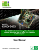
Table Of Contents
- 1 Introduction
- 2 Detailed Specifications
- 3 Unpacking
- 4 Connector Pinouts
- 4.1 Peripheral Interface Connectors
- 4.2 Internal Peripheral Connectors
- 4.2.1 Fan Connectors
- 4.2.2 Front Panel Connector
- 4.2.3 Digital Input/Output Connector
- 4.2.4 IDE Connector
- 4.2.5 LCD Backlight Connector
- 4.2.6 LVDS LCD connector
- 4.2.7 Power Connector
- 4.2.8 14-Pin Serial Port Connectors
- 4.2.9 10-Pin Serial Port Connectors
- 4.2.10 SATA Drive Connectors
- 4.2.11 SPDIF Connector
- 4.2.12 Internal USB Connectors
- 4.3 External Interface Connectors
- 5 Installation
- 6 AMI BIOS
- 7 Driver Installation
- A BIOS Options
- B DIO Interface
- C Watchdog Timer
KINO-9453 Mini-ITX Motherboard
Page IX
4.2.1 Fan Connectors................................................................................................ 32
4.2.2 Front Panel Connector .................................................................................... 33
4.2.3 Digital Input/Output Connector....................................................................... 34
4.2.4 IDE Connector................................................................................................. 35
4.2.5 LCD Backlight Connector................................................................................ 37
4.2.6 LVDS LCD connector ...................................................................................... 38
4.2.7 Power Connector ............................................................................................. 40
4.2.8 14-Pin Serial Port Connectors......................................................................... 41
4.2.9 10-Pin Serial Port Connectors......................................................................... 42
4.2.10 SATA Drive Connectors ................................................................................. 42
4.2.11 SPDIF Connector........................................................................................... 43
4.2.12 Internal USB Connectors............................................................................... 44
4.3 EXTERNAL INTERFACE CONNECTORS ....................................................................... 45
4.3.1 Audio Connectors............................................................................................. 46
4.3.2 CRT Connector ................................................................................................ 47
4.3.3 DVI Connector................................................................................................. 47
4.3.4 Ethernet Connectors ........................................................................................ 48
4.3.5 Keyboard/Mouse Connector ............................................................................ 50
4.3.6 Serial Port Connectors .................................................................................... 51
4.3.7 USB Connector ................................................................................................ 52
5 INSTALLATION .................................................................................................... 53
5.1 ANTI-STATIC PRECAUTIONS...................................................................................... 54
5.2 INSTALLATION CONSIDERATIONS.............................................................................. 55
5.2.1 Installation Notices .......................................................................................... 55
5.2.2 Installation Checklist ....................................................................................... 56
5.3 CPU, CPU COOLING KIT AND DIMM INSTALLATION .............................................. 57
5.3.1 Socket 479 CPU Installation............................................................................ 57
5.3.2 Cooling Kit CF-479B-RS Installation.............................................................. 60
5.3.3 DIMM Installation ........................................................................................... 62
5.4 JUMPER SETTINGS .................................................................................................... 63
5.4.1 AT/ATX Power Select Jumper Settings ............................................................ 64
5.4.2 Clear CMOS Jumper........................................................................................ 65
5.4.3 COM 3 Function Select Jumper....................................................................... 67
5.4.4 RS-422 or RS-486 Termination Resister .......................................................... 68