
Manual
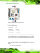
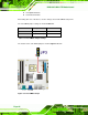
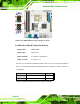
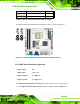
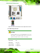

Table Of Contents
- 1 Introduction
- 2 Detailed Specifications
- 3 Unpacking
- 4 Connector Pinouts
- 4.1 Peripheral Interface Connectors
- 4.2 Internal Peripheral Connectors
- 4.2.1 Fan Connectors
- 4.2.2 Front Panel Connector
- 4.2.3 Digital Input/Output Connector
- 4.2.4 IDE Connector
- 4.2.5 LCD Backlight Connector
- 4.2.6 LVDS LCD connector
- 4.2.7 Power Connector
- 4.2.8 14-Pin Serial Port Connectors
- 4.2.9 10-Pin Serial Port Connectors
- 4.2.10 SATA Drive Connectors
- 4.2.11 SPDIF Connector
- 4.2.12 Internal USB Connectors
- 4.3 External Interface Connectors
- 5 Installation
- 6 AMI BIOS
- 7 Driver Installation
- A BIOS Options
- B DIO Interface
- C Watchdog Timer

KINO-9453 Mini-ITX Motherboard
Page 65
Figure 5-8: AT/ATX Power Select Jumper Location
5.4.2 Clear CMOS Jumper
Jumper Label: JP3
Jumper Type:
3-pin header
Jumper Settings: See
Table 5-3
Jumper Location: See
Figure 5-9
If the KINO-9453 fails to boot due to improper BIOS settings, the clear CMOS jumper
clears the CMOS data and resets the system BIOS information. To do this, use the jumper
cap to close pins 2 and 3 for a few seconds then reinstall the jumper clip back to pins 1
and 2.
If the “CMOS Settings Wrong” message is displayed during the boot up process, the fault
may be corrected by pressing the F1 to enter the CMOS Setup menu. Do one of the
following:
Enter the correct CMOS setting