
Manual
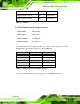
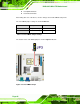
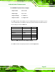
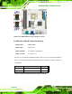
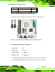
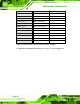
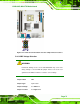

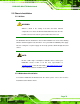
Table Of Contents
- 1 Introduction
- 2 Detailed Specifications
- 3 Unpacking
- 4 Connector Pinouts
- 4.1 Peripheral Interface Connectors
- 4.2 Internal Peripheral Connectors
- 4.2.1 Fan Connectors
- 4.2.2 Front Panel Connector
- 4.2.3 Digital Input/Output Connector
- 4.2.4 IDE Connector
- 4.2.5 LCD Backlight Connector
- 4.2.6 LVDS LCD connector
- 4.2.7 Power Connector
- 4.2.8 14-Pin Serial Port Connectors
- 4.2.9 10-Pin Serial Port Connectors
- 4.2.10 SATA Drive Connectors
- 4.2.11 SPDIF Connector
- 4.2.12 Internal USB Connectors
- 4.3 External Interface Connectors
- 5 Installation
- 6 AMI BIOS
- 7 Driver Installation
- A BIOS Options
- B DIO Interface
- C Watchdog Timer
KINO-9453 Mini-ITX Motherboard
Page 64
LVDS screen resolution selection JP2 8-pin header
RS-422 termination resister JP8 2-pin header
RS-485 termination resister JP9 2-pin header
Table 5-1: Jumpers
5.4.1 AT/ATX Power Select Jumper Settings
Jumper Label: JP5 and JP6
Jumper Type:
2-pin header
Jumper Settings: See
Table 5-2
Jumper Location:
See
Figure 5-8
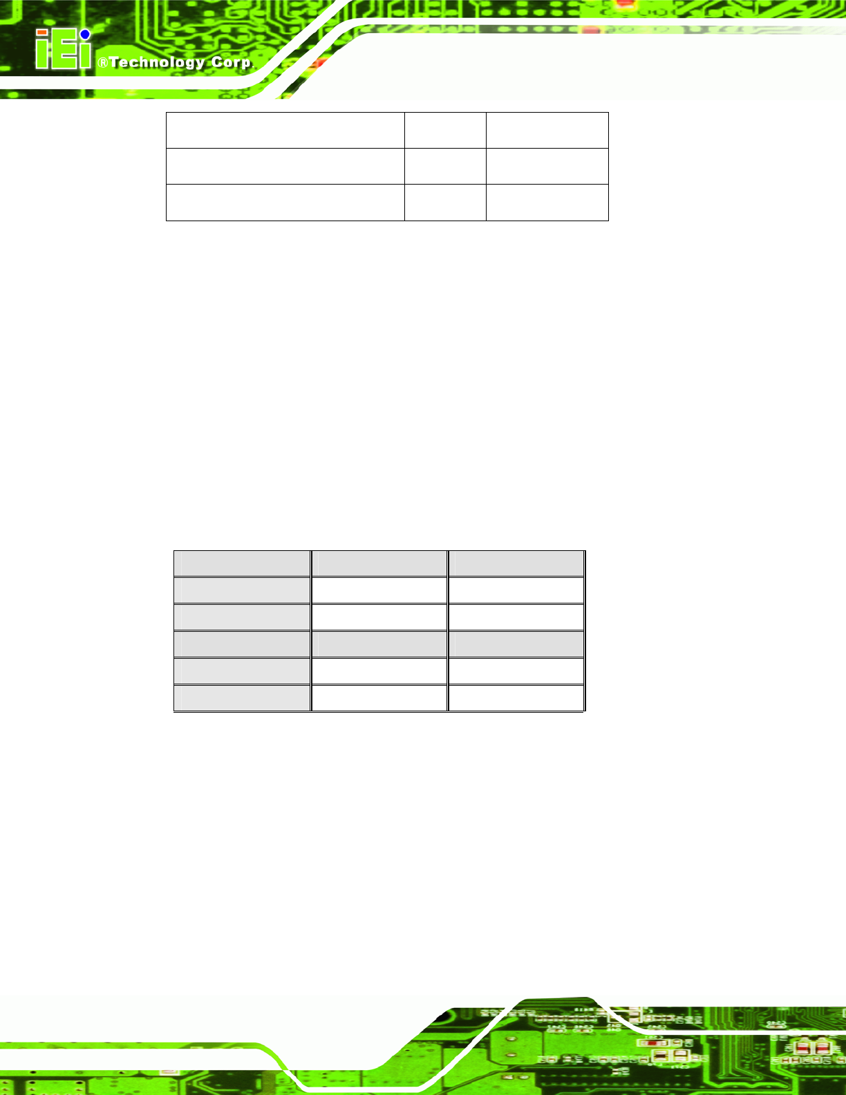
The AT/ATX Power Select jumper specifies the systems power mode as AT or ATX.
AT/ATX Power Select jumper settings are shown in
Table 5-2.
JP5 Description
Short Use ATX power Default
Open Use AT power
JP6 Description
Short Use AT power
Open Use ATX power Default
Table 5-2: AT/ATX Power Select Jumper Settings
The location of the AT/ATX Power Select jumper is shown in Figure 5-8 below.