
Manual

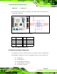
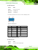

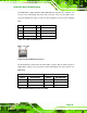
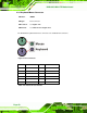
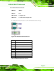

Table Of Contents
- 1 Introduction
- 2 Detailed Specifications
- 3 Unpacking
- 4 Connector Pinouts
- 4.1 Peripheral Interface Connectors
- 4.2 Internal Peripheral Connectors
- 4.2.1 Fan Connectors
- 4.2.2 Front Panel Connector
- 4.2.3 Digital Input/Output Connector
- 4.2.4 IDE Connector
- 4.2.5 LCD Backlight Connector
- 4.2.6 LVDS LCD connector
- 4.2.7 Power Connector
- 4.2.8 14-Pin Serial Port Connectors
- 4.2.9 10-Pin Serial Port Connectors
- 4.2.10 SATA Drive Connectors
- 4.2.11 SPDIF Connector
- 4.2.12 Internal USB Connectors
- 4.3 External Interface Connectors
- 5 Installation
- 6 AMI BIOS
- 7 Driver Installation
- A BIOS Options
- B DIO Interface
- C Watchdog Timer

KINO-9453 Mini-ITX Motherboard
Page 51
4.3.6 Serial Port Connectors
CN Label: COM1/2
CN Type:
DB-9
CN Location: See
Figure 4-14
CN Pinouts: See
Table 4-20 and Figure 4-20
The serial ports can be connected to a serial communications device directly.
Figure 4-20: External Serial Port Connector
PIN Description
1 DATA CARRIER DETECT (DCD)
2 RECEIVE DATA (RXD)
3 TRANSMIT DATA (TXD)
4 DATA TERMINAL READY (DTR)
5 GROUND (GND)
6 DATA SET READY (DSR)
7 REQUEST TO SEND (RTS)
8 CLEAR TO SEND (CTS)
9 RING INDICATOR (RI)
Table 4-20: External Serial Port Pinouts