
Manual

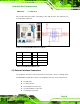
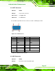

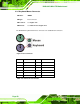
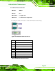

Table Of Contents
- 1 Introduction
- 2 Detailed Specifications
- 3 Unpacking
- 4 Connector Pinouts
- 4.1 Peripheral Interface Connectors
- 4.2 Internal Peripheral Connectors
- 4.2.1 Fan Connectors
- 4.2.2 Front Panel Connector
- 4.2.3 Digital Input/Output Connector
- 4.2.4 IDE Connector
- 4.2.5 LCD Backlight Connector
- 4.2.6 LVDS LCD connector
- 4.2.7 Power Connector
- 4.2.8 14-Pin Serial Port Connectors
- 4.2.9 10-Pin Serial Port Connectors
- 4.2.10 SATA Drive Connectors
- 4.2.11 SPDIF Connector
- 4.2.12 Internal USB Connectors
- 4.3 External Interface Connectors
- 5 Installation
- 6 AMI BIOS
- 7 Driver Installation
- A BIOS Options
- B DIO Interface
- C Watchdog Timer

KINO-9453 Mini-ITX Motherboard
Page 49
The KINO-9453 is equipped with two built-in GbE Ethernet controllers. The controllers can
connect to the LAN through two RJ-45 LAN connectors. There are two LEDs on the
connector indicating the status of LAN. The pin assignments are listed in the following
table:
PIN DESCRIPTION PIN DESCRIPTION
1 MDX0+ 5 MDX2-
2 MDX0- 6 MDX1-
3 MDX1+ 7 MDX3+
4 MDX2+ 8 MDX3-
Table 4-17: LAN1 and LAN2 Pinouts
Figure 4-18: RJ-45 Ethernet Connector
The RJ-45 Ethernet connector has two status LEDs, one green and one yellow. The green
LED indicates activity on the port and the yellow LED indicates the port is linked. See
Table 4-18.
SPEED LED ACT/LINK LED
STATUS DESCRIPTION STATUS DESCRIPTION
OFF 10Mbps connection OFF No link
ORANGE 100Mbps connection YELLOW Linked
GREEN 1Gbps connection BLINKING Data Activity
Table 4-18: RJ-45 Ethernet Connector LEDs