
Manual

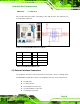
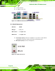
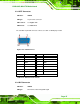

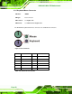

Table Of Contents
- 1 Introduction
- 2 Detailed Specifications
- 3 Unpacking
- 4 Connector Pinouts
- 4.1 Peripheral Interface Connectors
- 4.2 Internal Peripheral Connectors
- 4.2.1 Fan Connectors
- 4.2.2 Front Panel Connector
- 4.2.3 Digital Input/Output Connector
- 4.2.4 IDE Connector
- 4.2.5 LCD Backlight Connector
- 4.2.6 LVDS LCD connector
- 4.2.7 Power Connector
- 4.2.8 14-Pin Serial Port Connectors
- 4.2.9 10-Pin Serial Port Connectors
- 4.2.10 SATA Drive Connectors
- 4.2.11 SPDIF Connector
- 4.2.12 Internal USB Connectors
- 4.3 External Interface Connectors
- 5 Installation
- 6 AMI BIOS
- 7 Driver Installation
- A BIOS Options
- B DIO Interface
- C Watchdog Timer
KINO-9453 Mini-ITX Motherboard
Page 48
CN Location: See Figure 4-14
CN Pinouts: See
Figure 4-17 and Table 4-16
The KINO-9453 has an external DVI connector.
Figure 4-17 DVI-I Connector Pinout Locations
PIN Description PIN Description
PIN
Description
1 DTX2- 9 DTX1- 17 DTX0-
2 DTX2+ 10 DTX1+ 18 DTX0+
3 GND 11 GND 19 GND
4 N/C 12 N/C 20 N/C
5 N/C 13 N/C 21 N/C
6 SB_CK_C 14 PVDD1 22 GND
6 SB_DA_C 15 GND 23 DTXC+
8 V_SYNC 16 GND 24 DTXC-
C1 R C3 B 25 GND
C5 GND C6 GND 26 GND
C2 G C4 H_SYNC
Table 4-16: DVI-I Connector Pinouts
4.3.4 Ethernet Connectors
CN Label: LAN/USB1 and LAN/USB2
CN Type:
RJ-45
CN Location: See
Figure 4-14
CN Pinouts: See
Table 4-17