
Manual

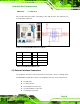
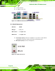

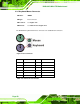
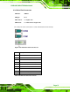

Table Of Contents
- 1 Introduction
- 2 Detailed Specifications
- 3 Unpacking
- 4 Connector Pinouts
- 4.1 Peripheral Interface Connectors
- 4.2 Internal Peripheral Connectors
- 4.2.1 Fan Connectors
- 4.2.2 Front Panel Connector
- 4.2.3 Digital Input/Output Connector
- 4.2.4 IDE Connector
- 4.2.5 LCD Backlight Connector
- 4.2.6 LVDS LCD connector
- 4.2.7 Power Connector
- 4.2.8 14-Pin Serial Port Connectors
- 4.2.9 10-Pin Serial Port Connectors
- 4.2.10 SATA Drive Connectors
- 4.2.11 SPDIF Connector
- 4.2.12 Internal USB Connectors
- 4.3 External Interface Connectors
- 5 Installation
- 6 AMI BIOS
- 7 Driver Installation
- A BIOS Options
- B DIO Interface
- C Watchdog Timer

KINO-9453 Mini-ITX Motherboard
Page 45
CN Pinouts: See Table 4-14
One 2x4 pin connector provides connectivity to two USB 2.0 ports. The USB ports are
used for I/O bus expansion.
Figure 4-13: Internal USB Connector Locations
PIN NO. DESCRIPTION PIN NO. DESCRIPTION
1 VCC 2 GND
3 DATA0- 4 DATA1+
5 DATA0+ 6 DATA1-
7 GND 8 VCC
Table 4-14: USB3 and USB4 Pinouts
4.3 External Interface Connectors
The peripheral connectors on the back panel are connected to devices externally when
the KINO-9453 is installed in a chassis. The peripheral connectors on the rear panel are:
2 x Audio jacks
1 x VGA connector
2 x RJ-45 Ethernet connectors
2 x Keyboard/mouse connectors
2 x Serial port connectors