
Manual
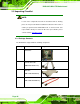
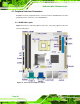
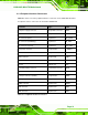
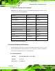
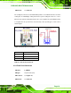
Table Of Contents
- 1 Introduction
- 2 Detailed Specifications
- 3 Unpacking
- 4 Connector Pinouts
- 4.1 Peripheral Interface Connectors
- 4.2 Internal Peripheral Connectors
- 4.2.1 Fan Connectors
- 4.2.2 Front Panel Connector
- 4.2.3 Digital Input/Output Connector
- 4.2.4 IDE Connector
- 4.2.5 LCD Backlight Connector
- 4.2.6 LVDS LCD connector
- 4.2.7 Power Connector
- 4.2.8 14-Pin Serial Port Connectors
- 4.2.9 10-Pin Serial Port Connectors
- 4.2.10 SATA Drive Connectors
- 4.2.11 SPDIF Connector
- 4.2.12 Internal USB Connectors
- 4.3 External Interface Connectors
- 5 Installation
- 6 AMI BIOS
- 7 Driver Installation
- A BIOS Options
- B DIO Interface
- C Watchdog Timer

KINO-9453 Mini-ITX Motherboard
Page 33
CN Pinouts: See Table 4-3
The cooling fan connectors on the KINO-9453 provide a 12 V, 500 mA current to one CPU
cooling fan, one Northbridge cooling fan and one system cooling fan. There is a “sense”
pin in the fan connector, which transfers the fan’s sense signal to the system BIOS in order
to recognize the fan speed. Please note that only some specific types of fans offer a
rotation signal.
Figure 4-2: Fan Connector Locations
PIN NO. DESCRIPTION
1 GND
2 +12V
3 Sense
Table 4-3: Fan Connector Pinouts
4.2.2 Front Panel Connector
CN Label: F_PANEL1
CN Type:
14-pin header (2x7)
CN Location: See
Figure 4-3
CN Pinouts: See
Table 4-4