
Manual
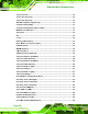
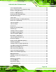
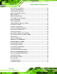
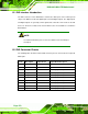
Table Of Contents
- 1 Introduction
- 2 Detailed Specifications
- 3 Unpacking
- 4 Connector Pinouts
- 4.1 Peripheral Interface Connectors
- 4.2 Internal Peripheral Connectors
- 4.2.1 Fan Connectors
- 4.2.2 Front Panel Connector
- 4.2.3 Digital Input/Output Connector
- 4.2.4 IDE Connector
- 4.2.5 LCD Backlight Connector
- 4.2.6 LVDS LCD connector
- 4.2.7 Power Connector
- 4.2.8 14-Pin Serial Port Connectors
- 4.2.9 10-Pin Serial Port Connectors
- 4.2.10 SATA Drive Connectors
- 4.2.11 SPDIF Connector
- 4.2.12 Internal USB Connectors
- 4.3 External Interface Connectors
- 5 Installation
- 6 AMI BIOS
- 7 Driver Installation
- A BIOS Options
- B DIO Interface
- C Watchdog Timer
KINO-9453 Mini-ITX Motherboard
Page 172
B.1 DIO Interface Introduction
The DIO connector on the KINO-9453 is interfaced to GIO ports on the iTE Super I/O
chipset. The DIO has both 4-bit digital inputs and 4-bit digital outputs. The digital inputs
and digital outputs are generally control signals that control the on/off circuit of external
devices or TTL devices. Data can be read or written to the selected address to enable the
DIO functions.
NOTE:
For further information, please refer to the datasheet for the iTE Super
I/O chipset.
B.2 DIO Connector Pinouts
The following table describes how the DIO connector pins are connected to the Super I/O
GPIO port 1.
Pin No Description Super I/O Pin Super I/O Pin Descripton
1 Ground N/A N/A
2 VCC N/A N/A
3 Output 0 GP14 General purpose I/O port 1 bit 4.
4 Output 1 GP15 General purpose I/O port 1 bit 5.
5 Output 2 GP16 General purpose I/O port 1 bit 6.
6 Output 3 GP17 General purpose I/O port 1 bit 7.
7 Input 0 GP10 General purpose I/O port 1 bit 0.
8 Input 1 GP11 General purpose I/O port 1 bit 1
9 Input 2 GP12 General purpose I/O port 1 bit 2
10 Input 3 GP13 General purpose I/O port 1 bit 3