
Manual

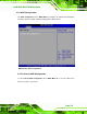
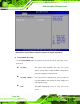
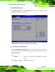
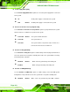
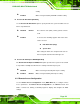
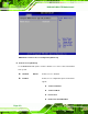
Table Of Contents
- 1 Introduction
- 2 Detailed Specifications
- 3 Unpacking
- 4 Connector Pinouts
- 4.1 Peripheral Interface Connectors
- 4.2 Internal Peripheral Connectors
- 4.2.1 Fan Connectors
- 4.2.2 Front Panel Connector
- 4.2.3 Digital Input/Output Connector
- 4.2.4 IDE Connector
- 4.2.5 LCD Backlight Connector
- 4.2.6 LVDS LCD connector
- 4.2.7 Power Connector
- 4.2.8 14-Pin Serial Port Connectors
- 4.2.9 10-Pin Serial Port Connectors
- 4.2.10 SATA Drive Connectors
- 4.2.11 SPDIF Connector
- 4.2.12 Internal USB Connectors
- 4.3 External Interface Connectors
- 5 Installation
- 6 AMI BIOS
- 7 Driver Installation
- A BIOS Options
- B DIO Interface
- C Watchdog Timer

KINO-9453 Mini-ITX Motherboard
Page 110
Power Supply Mode [ATX]
Use the Power Supply Mode BIOS option to to select the power supply that is connected
to the system.
AT
An AT power supply is connected to the system
ATX DEFAULT
An ATX power supply is connected to the system
Restore on AC Power Loss by IO [Power Off]
Use the Restore on AC Power Loss by IO BIOS option to specify what state the system
returns to if there is a sudden loss of power to the system.
Power Off DEFAULT
The system remains turned off
Power On
The system turns on
Last State
The system returns to its previous state. If it was on, it
turns itself on. If it was off, it remains off.
Resume on Ring [Disabled]
Use the Resume on Ring BIOS option to enable activity on the RI (ring in) modem line to
rouse the system from a suspend or standby state. That is, the system will be roused by
an incoming call on a modem.
Disabled DEFAULT
Wake event not generated by an incoming call
Enabled
Wake event generated by an incoming call
Resume on PME# [Disabled]
Use the Resume on PME# BIOS option to enable activity on the PCI PME (power
management event) controller to rouse the system from a suspend or standby state.
Disabled DEFAULT
Wake event not generated by PCI PME controller