
Manual

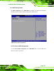
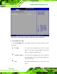
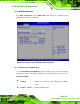
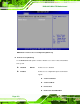
Table Of Contents
- 1 Introduction
- 2 Detailed Specifications
- 3 Unpacking
- 4 Connector Pinouts
- 4.1 Peripheral Interface Connectors
- 4.2 Internal Peripheral Connectors
- 4.2.1 Fan Connectors
- 4.2.2 Front Panel Connector
- 4.2.3 Digital Input/Output Connector
- 4.2.4 IDE Connector
- 4.2.5 LCD Backlight Connector
- 4.2.6 LVDS LCD connector
- 4.2.7 Power Connector
- 4.2.8 14-Pin Serial Port Connectors
- 4.2.9 10-Pin Serial Port Connectors
- 4.2.10 SATA Drive Connectors
- 4.2.11 SPDIF Connector
- 4.2.12 Internal USB Connectors
- 4.3 External Interface Connectors
- 5 Installation
- 6 AMI BIOS
- 7 Driver Installation
- A BIOS Options
- B DIO Interface
- C Watchdog Timer

KINO-9453 Mini-ITX Motherboard
Page 105
speed. To select a value, select the CPU Temp. Limit of Full option and enter a decimal
number between 000 and 127. The temperature range is specified below.
Minimum Value: 0°C
Maximum Value: 127°C
CPU Fan Start PWM [070]
The CPU Fan Start PWM option can only be set if the CPU FAN Mode Setting option is
set to Automatic Mode. Use the CPU Fan Start PWM option to select the PWM mode the
fan starts to rotate with after the temperature specified in the CPU Temp. Limit of Start is
exceeded. The Super I/O chipset supports 128 PWM modes. To select a value, select the
CPU Fan Start PWM option and enter a decimal number between 000 and 127. The
temperature range is specified below.
PWM Minimum Mode: 0
PWM Maximum Mode: 127
Slope PWM 1 [1 PWM]
The Slope PWM 1 option can only be set if the CPU FAN Mode Setting option is set to
Automatic Mode. Use the Slope PWM 1 option to select the linear rate at which the PWM
mode increases with respect to an increase in temperature. A list of available options is
shown below:
0 PWM
1 PWM
2 PWM
4 PWM
8 PWM
16 PWM
32 PWM
64 PWM