
Manual
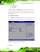
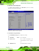
Table Of Contents
- 1 Introduction
- 2 Detailed Specifications
- 3 Unpacking
- 4 Connector Pinouts
- 4.1 Peripheral Interface Connectors
- 4.2 Internal Peripheral Connectors
- 4.2.1 Fan Connectors
- 4.2.2 Front Panel Connector
- 4.2.3 Digital Input/Output Connector
- 4.2.4 IDE Connector
- 4.2.5 LCD Backlight Connector
- 4.2.6 LVDS LCD connector
- 4.2.7 Power Connector
- 4.2.8 14-Pin Serial Port Connectors
- 4.2.9 10-Pin Serial Port Connectors
- 4.2.10 SATA Drive Connectors
- 4.2.11 SPDIF Connector
- 4.2.12 Internal USB Connectors
- 4.3 External Interface Connectors
- 5 Installation
- 6 AMI BIOS
- 7 Driver Installation
- A BIOS Options
- B DIO Interface
- C Watchdog Timer

KINO-9453 Mini-ITX Motherboard
Page 100
Serial Port1 Mode [Normal]
Use the Serial Port1 Mode option to select the transmitting and receiving mode for the
first serial port.
Normal
(Default) Serial Port 1 mode is normal
IrDA
Serial Port 1 mode is IrDA
ASK IR
Serial Port 1 mode is ASK IR
Serial Port2 Address [2F8/IRQ3]
Use the Serial Port2 Address option to select the Serial Port 2 base address.
Disabled
No base address is assigned to Serial Port 2
2F8/IRQ3 DEFAULT
Serial Port 2 I/O port address is 3F8 and the interrupt
address is IRQ3
3E8/IRQ4
Serial Port 2 I/O port address is 3E8 and the interrupt
address is IRQ4
2E8/IRQ3
Serial Port 2 I/O port address is 2E8 and the interrupt
address is IRQ3
Serial Port2 Mode [Normal]
Use the Serial Port2 Mode option to select the Serial Port2 operational mode.
Normal DEFAULT
Serial Port 2 mode is normal
IrDA
Serial Port 2 mode is IrDA
ASK IR
Serial Port 2 mode is ASK IR
Serial Port3 Address [3E8]
Use the Serial Port3 Address option to select the base addresses for serial port 3