
User guide

KINO-9453 Mini-ITX Motherboard
Page 50
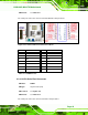
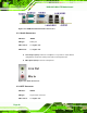
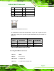
Figure 4-18 DVI-I Connector Pinout Locations
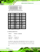
PIN Description PIN Description
PIN
Description
1 DTX2- 9 DTX1- 17 DTX0-
2 DTX2+ 10 DTX1+ 18 DTX0+
3 GND 11 GND 19 GND
4 N/C 12 N/C 20 N/C
5 N/C 13 N/C 21 N/C
6 SB_CK_C 14 PVDD1 22 GND
6 SB_DA_C 15 GND 23 DTXC+
8 V_SYNC 16 GND 24 DTXC-
C1 R C3 B 25 GND
C5 GND C6 GND 26 GND
C2 G C4 H_SYNC
Table 4-17: DVI-I Connector Pinouts
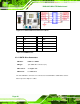
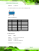
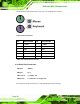
4.3.4 Ethernet Connectors
CN Label: LAN/USB1 and LAN/USB2
CN Type:
RJ-45
CN Location: See
Figure 4-15
CN Pinouts: See
Table 4-18
The KINO-9453 is equipped with two built-in GbE Ethernet controllers. The controllers can
connect to the LAN through two RJ-45 LAN connectors. There are two LEDs on the
connector indicating the status of LAN. The pin assignments are listed in the following
table: