
User guide


KINO-9453 Mini-ITX Motherboard
Page 34
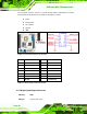
The front panel connector connects to several external switches and indicators to monitor
and control the motherboard. These indicators and switches include:
Power
Power button
Reset button
Speaker
HDD
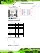
Figure 4-3: Front Panel Connector Location
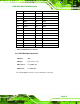
PIN NO. DESCRIPTION PIN NO. DESCRIPTION
1 Power LED+ 2 Speaker+
3 NC 4 NC
5 Power LED- 6 NC
7 Power Button# 8 Speaker-
9 Power Button 10 NC
11 IDE LED+ 12 Reset Button
13 IDE LED- 14 Reset Button#
Table 4-4: Front Panel Connector Pinouts
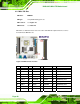
4.2.3 Digital Input/Output Connector
CN Label: DIO1
CN Type:
10-pin header (2x5)