
Manual

iVW-UD322iVW-UD322 Video Wall Controller
15
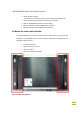
3.5 Connect Cables
The cables that need to be attached are listed below:
Video input cable(Dual-link DVI) – from the video source or computer
Video output cables – attached to the LCD panels. Make sure the cables are
connected to the correct monitors securely.
Power cable – from the power adapter
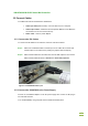
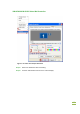
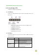
3.5.1 Connect the DVI Cables
To connect the DVI cables to the video box, follow the instructions below.
Step 1: Attach the included DVI cable to the DVI input on the video wall controller and
the DVI output on the video source (usually the graphic card of computer).
Step 2: Attach the DVI cables from the video wall controller DVI outputs to the monitors.
Attach the DVI cables as shown in Section 3.2: Panel Setup Options. Step 2:
Figure 3-2: iVW-UD322 Video Input
3.5.2 Connect the iVW-UD322 to the Power Supply
Connect the included AC adaptor into an AC power supply then connect the DC plug to
the video wall controller.
Turn oniVW-UD322by using the power switch located at the back panel.