iVW-UD322iVW-UD322 Video Wall Controller MODEL: iVW-UD322 / iVW-UD322F Video Wall Controller Supports 2 x 2, 2 x 1, 3x1, 1x3, 4x1 & 1x4 Video Wall Array User Manual Rev. 1.
iVW-UD322iVW-UD322 Video Wall Controller Copyright COPYRIGHT NOTICE The information in this document is subject to change without prior notice in order to improve reliability, design and function and does not represent a commitment on the part of the manufacturer. In no event will the manufacturer be liable for direct, indirect, special, incidental, or consequential damages arising out of the use or inability to use the product or documentation, even if advised of the possibility of such damages.
iVW-UD322iVW-UD322 Video Wall Controller Table of Contents COPYRIGHT ................................................................................................................... II TABLE OF CONTENTS ................................................................................................ III LIST OF FIGURES ..........................................................................................................V LIST OF TABLES .................................................................
iVW-UD322iVW-UD322 Video Wall Controller 3.3 INSTALL LCD PANELS .............................................................................................. 13 3.4 MOUNT THE VIDEO WALL CONTROLLER .................................................................... 14 3.5 CONNECT CABLES .................................................................................................... 15 3.5.1 Connect the DVI Cables................................................................................... 15 3.5.
iVW-UD322iVW-UD322 Video Wall Controller List of Figures Figure 1-1: iVW-UD322 overview .............................................................................................. 2 Figure 1-2: iVW-UD322 Front Panel .......................................................................................... 3 Figure 1-3: iVW-UD322 Rear Panel ........................................................................................... 4 Figure 1-4: iVW-UD322 Dimensions .......................................
iVW-UD322iVW-UD322 Video Wall Controller Figure 4-23: SmartOSD Master Control Panel........................................................................ 41 Figure 4-24: SmartOSD Slave Control Panel .......................................................................... 43 Figure 4-25: SmartOSD Master Data....................................................................................... 45 Figure 4-26: SmartOSD About Page ............................................................................
iVW-UD322iVW-UD322 Video Wall Controller List of Tables Table 1-1: Technical Specifications .......................................................................................... 5 Table 2-1: Package List Contents ............................................................................................. 8 Table 4-1: OSD Menu Structure .............................................................................................. 23 Table 4-2: SmartOSD Menu Structure ..................................
iVW-UD322iVW-UD322 Video Wall Controller Chapter 1 1 Introduction 1
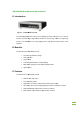
iVW-UD322iVW-UD322 UD322 Video Wall Controller 1.1 Introduction Figure 1-1: iVW-UD322 UD322 overview The iVW-UD322video video wall controller is for displaying a single video input on an array of monitors, implementing a large display without the inherent high costs of a single large monitor. The iVW-UD322 UD322 is for large displays where high definition video output is also essential. 1.
iVW-UD322iVW-UD322 Video Wall Controller 1.4 External Interfaces, Switches and LEDs This section gives and overview of the connectors, switches and indicators on the iVW-UD322. 1.4.1 Front Panel The front panel has the following buttons and indicators: Power LED indicator Video output LED indicator Video input LED indicators OSD buttons Infrared sensor Figure 1-2: iVW-UD322 Front Panel 1.4.
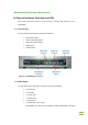
iVW-UD322iVW-UD322 Video Wall Controller Figure 1-3: iVW-UD322 Rear Panel 1.5 Technical Specifications Video box features are listed in Table 1-1. See Chapter 2 for details. Specification Detail Model Name iVW-UD322 Main Features 1. Multiple viewing modes 2. Software OSD 3. Remote control (optional) 4. Bezel masking Inputs 1 x Dual-link DVI-D Outputs 4 x Single-link DVI-D Dimensions (W x D x H) 230 mm x 180 mm x 47 mm Cooling Fanless Input Resolution See Section 3.
iVW-UD322iVW-UD322 Video Wall Controller Specification Detail Temperature 0ºC – 40ºC Power Consumption 18 W Table 1-1: Technical Specifications 1.6 Dimensions The dimensions are shown below.
iVW-UD322iVW-UD322 Video Wall Controller Chapter 2 2 Packing List 6
iVW-UD322iVW-UD322 UD322 Video Wall Controller 2.1 Anti-static static Precautions When the iVW-UD322 UD322 is unpacked, please do the following: Make sure the packing box is facing upwards so the iVW-UD322 iVW does not fall out of the box. Make sure all the components shown in Section 2.2 are present. 2.2 Packing List NOTE: If any parts are missing, stop tthe installation and contact a sales representative by emailing ds_sales@indstech.com..
iVW-UD322iVW-UD322 Video Wall Controller No.
iVW-UD322iVW-UD322 Video Wall Controller Chapter 3 3 Installation 9
iVW-UD322iVW-UD322 Video Wall Controller 3.1 Requirements NOTE: The iVW-UD322 requires all attached components to comply with the specifications. If the specifications are not met, the iVW-UD322 may not work as desired. Before installation, make sure the minimum hardware requirements are met. 3.1.1 Video Card The video card output resolution must meet the input requirements for the chosen output mode.
iVW-UD322iVW-UD322 Video Wall Controller 3.2 Panel Setup Options The iVW-UD322videl wall controller supportspanel setup as shown in the subsections below. Dark black sections indicate the panels for the installation, and the bold number indicate which video output. 3.2.1 2 x 2 To setup four monitors as a 2 by 2 array, connect the monitors as shown below.
iVW-UD322iVW-UD322 Video Wall Controller 3.2.2 2 x 1 To setup two monitors horizontally, connect the monitors as shown below. 3.2.3 3 x 1 To setup three monitors horizontally, connect the monitors as shown below. 3.2.4 4 x 1 To setup four monitors horizontally, connect the monitors as shown below.
iVW-UD322iVW-UD322 Video Wall Controller 3.2.5 1 x 3 To setup three monitors vertically, connect the monitors as shown below. 3.2.6 1 x 4 To setup four monitors vertically, connect the monitors as shown below. 3.3 Install LCD Panels The monitors should be installed in one of the configurations shown in the previous section.
iVW-UD322iVW-UD322 Video Wall Controller Use all identical monitors * Recommand to use monitors without control buttons around side of the bezel, otherwise the buttons will be blocked by other panels Minimize gaps between panels for the best image Maintain consistent horizontal gaps between monitors Maintain consistent vertical gaps between monitors 3.4 Mount the video wall controller The iVW-UD322video wall controller must be placed on a table, desk or other firm surface.
iVW-UD322iVW-UD322 Video Wall Controller 3.5 Connect Cables The cables that need to be attached are listed below: Video input cable(Dual-link DVI) – from the video source or computer Video output cables – attached to the LCD panels. Make sure the cables are connected to the correct monitors securely. Power cable – from the power adapter 3.5.1 Connect the DVI Cables To connect the DVI cables to the video box, follow the instructions below.
iVW-UD322iVW-UD322 Video Wall Controller 3.6 Resolution and Display Mode Charts The display modes are automatically set according to the input resolution. The input and output resolutions for iVW-UD322 are shown in the following subsections.
iVW-UD322iVW-UD322 Video Wall Controller Mode Input Output Vertical Resolution Resolution Hz 3840x2160 1920x1080 60 16:9 3840x2400 1920x1200 60 16:10 2560x1920 1280x960 60 1280x960 640x480 60 3392x1920 1696x960 60 1696x960 848x480 60 2732x1536 1366x768 60 16:9 3392x480 848x480 60 16:9 3200x600 800x600 60 4:3 3840x600 960x600 60 16:10 4094x768 1024x768 60 4:3 1024x3072 1024x768 60 4:3 1280x3200 1280x800 60 16:10 1280x4095 1280x1024 60 5:4 1360x3072
iVW-UD322iVW-UD322 Video Wall Controller Mode Input Output Vertical Resolution Resolution Hz 1280x3072 1280x1024 60 5:4 1360x2304 1360x768 60 16:9 1366x2304 1366x768 60 16:9 Monitor Ratio / Notes 3.7 Setting Video Wall Controller and Graphics Card Resolution To setup the resolution on the graphics card and on the video wall controller, follow the instructions below. Step 3: Turn on the video wall controller. Step 4: Turn on the computer.
iVW-UD322iVW-UD322 Video Wall Controller Figure 3–4: Video Card Output Resolution Step 3: Select the "Advanced" video card setting. Step 4: Uncheck "Hide modes that this monitor cannot display".
iVW-UD322iVW-UD322 Video Wall Controller Figure 3–5: Don't Hide Display Modes not supported by the monitor 3.8 Bezel Compensation The bezel compensation setting compensates for the gaps between monitors in the video wall array. The bezel compensation sizes the image slightly larger than the visible screen to make the images on adjacent monitors line-up correctly. The bezel settings are set using the smartOSD (Section 4.1) or OSD menu (Section 4.1).
iVW-UD322iVW-UD322 Video Wall Controller Chapter 4 4 OSD Functions 21
iVW-UD322iVW-UD322 UD322 Video Wall Controller 4.1 On ScreenDisplay Display ((OSD) The OSD menu functions are described below. 4.1.1 OSD Buttons Customer can control iVW iVW-UD322 through the OSD D by operating the buttons on front panel as below Figure 4-1:: OSD Buttons Menu.. Enters the OSD, selects items and sets the new values entered. Left.. Moves the selection le left. Right.. Moves the selection right. Up.. Moves the selection up. Down.. Moves the selection down. Enter.
iVW-UD322iVW-UD322 Video Wall Controller Menu Options Description Slave Mask Setting DVI DVI 1-4: Update linked slave controllers’ (Note: These settings settings can only be changed DVI x: Update setting for an individual slave while Link function is controller when link is off.
iVW-UD322iVW-UD322 Video Wall Controller 4.1.2.1 Mask Control Mask control compensates for the gaps between monitors by displaying the images slightly larger than the visible screen. Figure 4-2: Mask Control Mask Enable / disable the mask function. With the mask function on, the image is adjusted to compensate for gaps between monitors in the video wall. Available selections: Off On Right Left Top Buttom X Adjusts the value of compensation from left to right.
iVW-UD322iVW-UD322 Video Wall Controller 4.1.2.2 Link Control Link control allows the master controller to automatically adjust the mask settings of the attached slave controllers. Figure 4-3: Link Control LINK This setting toggles the link setting on and off.
iVW-UD322iVW-UD322 Video Wall Controller 4.1.2.3 Slave Mask Setting The slave mask setting shows the mask setting on the slave video boxes. Figure 4-4: Slave Mask Setting DVI This setting indicates which slaves settings are shown. DVI 1-4 Mask link is on, and all slaves have the same setting DVI 1 Mask link is off. The first slave controller's settings are shown DVI 2 Mask link is off. The second slave controller's settings are shown DVI 3 Mask link is off.
iVW-UD322iVW-UD322 Video Wall Controller 4.1.2.4 Settings This menu shows the output resolution of the attached monitors. Figure 4-5: Settings OUT This setting is the output resolution to the attached monitor or slave controller. MODE This setting shows the video output mode of the video box.
iVW-UD322iVW-UD322 Video Wall Controller 4.1.2.5 Warning Indicates that the output resolution on the computer should be adjusted to the shown value. Figure 4-6: Warning Change Setting Shows the value that the computer video output should be set to. 4.1.2.6 Information The information menu shows the current input and output resolutions.
iVW-UD322iVW-UD322 Video Wall Controller OUT Displays the current output resolution. IN Displays the current input resolution 4.1.2.7 Sync and Power The sync and power menu toggles sync and turns the power on and off.
iVW-UD322iVW-UD322 Video Wall Controller SYNC Enable/disable the synchronization between video wall controllers with fiber optical cable. (iVW-UD322F only) SCAN Toggles the scan function between the master video wall controller and the slave video wall controllers. Video wall controller will scan the devices connecting to DVI output ports only when the SCAN option turns on. The default setting is off. 4.1.2.
iVW-UD322iVW-UD322 Video Wall Controller FW Displays the current firmware version. 4.1.2.9 Serial Number The serial number page shows the model name and serial number of the video wall controller. Figure 4-10: Serial Number Model Name The first line displays the model name.
iVW-UD322iVW-UD322 UD322 Video Wall Controller 4.1.3 Remote Control The iVW-UD322has has an optional remote control for easy configuration of OSD settings. 491H491H Figure 4-11 shows the remote control and its function keys. Power. Turns the controller on and off. Menu.. Enters the OSD, selects items and sets the newvalues entered. Left. Moves the selection left. Right. Moves the selection right. Up. Moves the selection up. Down. Moves the selection down. Enter. Exits from any menu.
iVW-UD322iVW-UD322 Video Wall Controller 4.2 SmartOSD iNDSSmartOSD is a powerfulmanagement software solution for managing video wall controllerswith PCs under popular Microsoft Windows environment. SmartOSD provides a more flexible wayon controlling the video wall controller and monitor settings.
iVW-UD322iVW-UD322 Video Wall Controller Step 2: Click the “Allow” option if the security warning appears in Windows Vista or Windows 7. Step 3: The welcome screen appears as below. Figure 4-14: SmartOSD Welcome Screen Step 4: Click NEXT to continue.
iVW-UD322iVW-UD322 Video Wall Controller Step 5: The Select Destination Folder window appears (Figure 4-15).Change the installation directory if required. Click NEXT to continue Figure 4-15: SmartOSD Installation Directory Step 6: The program is now ready to install. Click “Install” to continue(Figure 4-15).
iVW-UD322iVW-UD322 Video Wall Controller Step 7: Specify a new name or folder for the Start Menu entry if required. Click NEXT to continue. Step 8: The Additional Tasks window appears (Figure 4-17). Figure 4-17: SmartOSDAdditional Tasks Step 9: Check the extra items that should be added (optional). Click NEXT to continue. Step 10: The Ready to Installdialog will show be displayed (Figure 4-18).
iVW-UD322iVW-UD322 Video Wall Controller Figure 4-18: SmartOSDReady to Install Step 11: Confirm the installation by clicking INSTALL in the screen above. Step 12: The Installation Progressdialogwill display the progress of the software installation (Figure 4-19).
iVW-UD322iVW-UD322 Video Wall Controller Step 13: The following dialog is displayed when the installation is completed Figure 4-20: SmartOSD Installation Complete Step 14: Click FINISH to close the installation wizard.
iVW-UD322iVW-UD322 Video Wall Controller 4.2.2 Using SmartOSD The following table describe the complete functions of SmartOSD(Table 4-2).
iVW-UD322iVW-UD322 Video Wall Controller 4.2.2.1 PC Setting The PC Setting page sets the command port to use for data communication between the video box and the computer. Figure 4-21: smartOSD PC Setting DVI Selects the DVI input signal. Identify Detect and identify the video wall controller on the DVI link. S/N Displays the controller's serial number.
iVW-UD322iVW-UD322 Video Wall Controller 4.2.2.2 Master Control Panel The control panel page presents all the adjustable settings for the video wall controller. Figure 4-22: SmartOSD Master Control Panel Mask Control The Mask Control options allow the images to be adjusted to compensate for the gaps between monitors in the video array.
iVW-UD322iVW-UD322 Video Wall Controller MU The top side is fixed and the bottom side changes when adjustments are made (for top side controller in the dual controller configuration) MD The bottom side is fixed and the top side changes when adjustments are made (for bottom side controller in the dual controller configuration) Power Control Turns the power on and off. Value of X The Value of X sets the horizontal bezel compensation.
iVW-UD322iVW-UD322 Video Wall Controller 4.2.2.3 Slave Control Panel Figure 4-23: SmartOSD Slave Control Panel Mask Control Link Enable/disable the mask link between the master and slaves. When the mask control link has been disabled, the slave controllers can be managed by the following options. DVI Number DVI number selects the target slave controller to be managed.
iVW-UD322iVW-UD322 Video Wall Controller On The value of X and the value of Y can be adjusted to compensate for gaps between monitors (for single controller) MR The right side is fixed and the left side changes when adjustments are made (for right side controller in the dual controller configuration) ML The left side is fixed and the right side changes when adjustments are made (for left side controller in the dual controller configuration) MU The top side is fixed and the bottom side changes
iVW-UD322iVW-UD322 Video Wall Controller 4.2.2.4 Master Data The Master Data menu displays the current settings of the master video wall controller.
iVW-UD322iVW-UD322 Video Wall Controller 4.2.2.5 About Page The About Page shows general information about the SmartOSD.
iVW-UD322iVW-UD322 Video Wall Controller Chapter 5 5 Troubleshooting and Maintenance 5.1 Maintenance Overview NOTE: There are no user-serviceable parts inside. Make sure to carefully follow all the instructions in this section to diagnose any problems. If the problem persists, email ds_sales@indstech.com for help from an authorized sales representative 5.2 Troubleshooting This section provides some simple troubleshooting suggestions. 5.2.
iVW-UD322iVW-UD322 Video Wall Controller 5.2.1.1 Check Monitor Power Step 1: Make sure the monitor is turned on. Step 2: Check the power source for the monitor. Step 3: Make sure the power source has the correct power rating (check panel specifications for details). Step 4: Make sure the LCD panel power cables are properly secured to the monitor and e tp 0 : to the power source.S 5.2.1.2 Check Monitor Video Connection Make sure the video cable is linkedproperly.
iVW-UD322iVW-UD322 Video Wall Controller 5.2.3.2 Check Source Video Connection Make sure the video cable is linkedproperly. Step 1: Make sure a Dual-link DVIcablewith length less than 5 M is connected between PC andiVW-UD322. Step 2: Fasten the screws on the connector of video cable.