
Instruction Manual


ITDB-100L Barcode Reader
Page 19
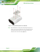
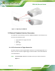
Step 2: Align the connectors. Align the 6-pin plug on the trigger connection cable with
the 6-pin connector on the ITDB-100L. See
Figure 3-4.
Figure 3-4: Trigger Connection
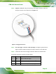
Step 3: Insert the trigger connection cable 6-pin plug. Once aligned, gently insert the
trigger connection cable 6-pin plug into the 6-pin connector on the ITDB-100L.
Step 4: Connect the other end of the trigger connection cable to an external device.
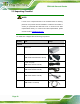
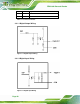
The pinouts of the 6-pin connector are shown below:
Pin Color Signal
1 Red Output of LED Flash Trigger
2 Black Ground for the Output of LED Flash Trigger
3 Blue Input of Interrupt Trigger
4 Black Ground for the Input of Interrupt Trigger