
User Manual

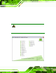
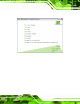


Table Of Contents
- 1 Introduction
- 2 Unpacking
- 3 Connectors
- 3.1 Peripheral Interface Connectors
- 3.2 Internal Peripheral Connectors
- 3.2.1 ATX Power Enable Connector
- 3.2.2 Audio Connector (10-pin)
- 3.2.3 Backlight Inverter Connector
- 3.2.4 Battery Connector
- 3.2.5 CompactFlash® Socket
- 3.2.6 Digital Input/Output (DIO) Connector
- 3.2.7 Fan Connector (+5V)
- 3.2.8 Floppy Disk Connector
- 3.2.9 Front Panel Connector (8-pin)
- 3.2.10 IDE Connector (40-pin)
- 3.2.11 Infrared Interface Connector (5-pin)
- 3.2.12 Keyboard/Mouse Connector
- 3.2.13 Parallel Port Connector
- 3.2.14 Power Connector
- 3.2.15 SATA Drive Connectors (Optional)
- 3.2.16 Serial Port Connector (RS-232/422/485)
- 3.2.17 TTL Connector
- 3.2.18 Internal USB Connectors
- 3.2.19 -VCC Power Connector
- 3.3 External Peripheral Interface Connectors
- 4 Installation
- 5 BIOS Screens
- A BIOS Menu Options
- B One Key Recovery
- C Terminology
- D Watchdog Timer
- E Hazardous Materials Disclosure

IOWA-LX-600 Half-size CPU Card
Page 65
NOTE:
The following sections will completely describe the menus listed below
and the configuration options available to use rs.
The following menu options are seen in 6BIOS Menu 1.
St andard CMOS Featu res: Chang es the basic system configuration.
Advanced BIOS Features: Changes the advanced system settings.
Advanced Chipset Featu res: Changes the chipset configuration features.
Integrated Peripherals: Changes the settings for integrated peripherals.
Power Management Setu p: Configures power saving options.
PnP/PCI Configurations: Changes the advanced PCI/PnP settings.
PC Health Status: Monitors essential system parameters.
The following user config urable options are also available in
6BIOS Menu 1:
Load Fail-Safe Defaults
Use the Load Fail-Safe Defaults option to load failsafe default values for each BIOS
parameter in the setup menus. Pre s s F6 for this operation on any page.
Load Optimized Default s
Use the Load Optimized Defaults option to load optimal default values for each BIOS
parameter in the setup menus. Pre s s F7 for this operation on any page.
Set Supervisor Password
Use the Set Supervisor Password option to set the supervisor password. By default, no
supervisor password i s set. To install a superviso r password, sele ct this field and enter the
password. After this option is selected, a red dialogue box appears with “Enter
Password: ”. Type the password and press E
NTER. Retype the original password into the
“Confirm Password: ” dialogue box and press E
NTER. To disable the password, simply
press E
NTER in the “Enter Password: ” dialogue box, then press any key in the
“Password Disabled !!!” dialogue box.