
User Manual
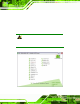
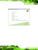

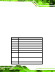
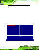

Table Of Contents
- 1 Introduction
- 2 Unpacking
- 3 Connectors
- 3.1 Peripheral Interface Connectors
- 3.2 Internal Peripheral Connectors
- 3.2.1 ATX Power Enable Connector
- 3.2.2 Audio Connector (10-pin)
- 3.2.3 Backlight Inverter Connector
- 3.2.4 Battery Connector
- 3.2.5 CompactFlash® Socket
- 3.2.6 Digital Input/Output (DIO) Connector
- 3.2.7 Fan Connector (+5V)
- 3.2.8 Floppy Disk Connector
- 3.2.9 Front Panel Connector (8-pin)
- 3.2.10 IDE Connector (40-pin)
- 3.2.11 Infrared Interface Connector (5-pin)
- 3.2.12 Keyboard/Mouse Connector
- 3.2.13 Parallel Port Connector
- 3.2.14 Power Connector
- 3.2.15 SATA Drive Connectors (Optional)
- 3.2.16 Serial Port Connector (RS-232/422/485)
- 3.2.17 TTL Connector
- 3.2.18 Internal USB Connectors
- 3.2.19 -VCC Power Connector
- 3.3 External Peripheral Interface Connectors
- 4 Installation
- 5 BIOS Screens
- A BIOS Menu Options
- B One Key Recovery
- C Terminology
- D Watchdog Timer
- E Hazardous Materials Disclosure
IOWA-LX-600 Half-size CPU Card
Page 64
F10 Save changes and Exit BIOS
Table 5-1: BIOS Navigation Keys
5.1.3 Getting Help
When F1 is pressed a small help window describing the appropriate keys to use and the
possible selections for the highlighted item appears. To exit the Help Window press E
SC
or the F1 key again.
5.1.4 Unable to Reboot After Configuration Changes
If the system cannot be booted after change s are made, re store the CMOS defaul ts. Refer
to Section
63.2.4 for more information.
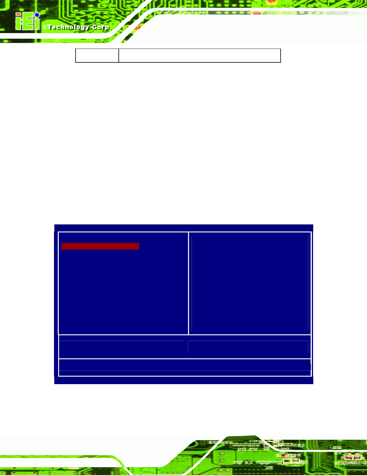
5.1.5 Main BIOS Menu
Once the BIOS opens, the main menu (6BIOS Menu 1) appears.
Phoenix - AwardBIOS CMOS Setup Utility
> Standard CMOS Features
> Advanced BIOS Features
> Advanced Chipset Features
> Integrated Peripherals
> Power Management Setup
> PnP/PCI Configurations
> PC Health Status
Load Fail-Safe Defaults
Load Optimized Defaults
Set Supervisor Password
Set User Password
Save & Exit Setup
Exit Without Saving
Esc=Quit
F10=Save & Exit Setup
↑ ↓=Select Item
Time, Date, Hard Disk Type...
BIOS Menu 1: Award BIOS Setup Utility