
User Manual
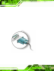


Table Of Contents
- 1 Introduction
- 2 Unpacking
- 3 Connectors
- 3.1 Peripheral Interface Connectors
- 3.2 Internal Peripheral Connectors
- 3.2.1 ATX Power Enable Connector
- 3.2.2 Audio Connector (10-pin)
- 3.2.3 Backlight Inverter Connector
- 3.2.4 Battery Connector
- 3.2.5 CompactFlash® Socket
- 3.2.6 Digital Input/Output (DIO) Connector
- 3.2.7 Fan Connector (+5V)
- 3.2.8 Floppy Disk Connector
- 3.2.9 Front Panel Connector (8-pin)
- 3.2.10 IDE Connector (40-pin)
- 3.2.11 Infrared Interface Connector (5-pin)
- 3.2.12 Keyboard/Mouse Connector
- 3.2.13 Parallel Port Connector
- 3.2.14 Power Connector
- 3.2.15 SATA Drive Connectors (Optional)
- 3.2.16 Serial Port Connector (RS-232/422/485)
- 3.2.17 TTL Connector
- 3.2.18 Internal USB Connectors
- 3.2.19 -VCC Power Connector
- 3.3 External Peripheral Interface Connectors
- 4 Installation
- 5 BIOS Screens
- A BIOS Menu Options
- B One Key Recovery
- C Terminology
- D Watchdog Timer
- E Hazardous Materials Disclosure
IOWA-LX-600 Half-size CPU Card
Page 59
Step 3: Secure the connector. Secure the serial device conn ector to the external
interface by tightening the two retention screws on either side of the connector.
Step 0:
4.9.4 VGA Monitor Connection
The IOWA-LX-600 has a single female DB-15 connector on the external peripheral
interface panel. The DB-15 connector is connected to a CRT or VGA monitor. To connect
a monitor to the IOWA-LX-600, please follow the instructions below.
Step 1: Locate the female DB-15 connector. The location of the female DB-15
connector is shown in Chapter 3.
Step 2: Align the VGA connector. Align the male DB-15 connector on the VGA screen
cable with the female DB-15 conne ctor o n the external peripheral interface.
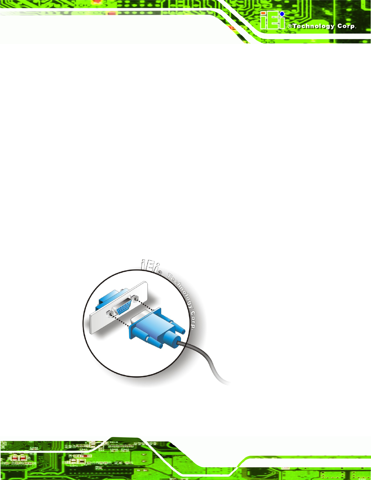
Step 3: Insert the VGA connector. Once the connectors are properly aligned with the
insert the male connector from the VGA screen into the female connector on the
IOWA-LX-600. See
6Figure 4-15.
Figure 4-15: VGA Connector