
User Manual
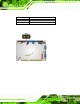
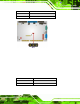
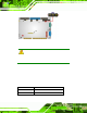
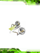
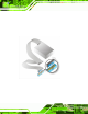
Table Of Contents
- 1 Introduction
- 2 Unpacking
- 3 Connectors
- 3.1 Peripheral Interface Connectors
- 3.2 Internal Peripheral Connectors
- 3.2.1 ATX Power Enable Connector
- 3.2.2 Audio Connector (10-pin)
- 3.2.3 Backlight Inverter Connector
- 3.2.4 Battery Connector
- 3.2.5 CompactFlash® Socket
- 3.2.6 Digital Input/Output (DIO) Connector
- 3.2.7 Fan Connector (+5V)
- 3.2.8 Floppy Disk Connector
- 3.2.9 Front Panel Connector (8-pin)
- 3.2.10 IDE Connector (40-pin)
- 3.2.11 Infrared Interface Connector (5-pin)
- 3.2.12 Keyboard/Mouse Connector
- 3.2.13 Parallel Port Connector
- 3.2.14 Power Connector
- 3.2.15 SATA Drive Connectors (Optional)
- 3.2.16 Serial Port Connector (RS-232/422/485)
- 3.2.17 TTL Connector
- 3.2.18 Internal USB Connectors
- 3.2.19 -VCC Power Connector
- 3.3 External Peripheral Interface Connectors
- 4 Installation
- 5 BIOS Screens
- A BIOS Menu Options
- B One Key Recovery
- C Terminology
- D Watchdog Timer
- E Hazardous Materials Disclosure
IOWA-LX-600 Half-size CPU Card
Page 53
4.8 Internal Peripheral Device Connections
This section outlines the installation of peripheral de vices to the onboard connectors
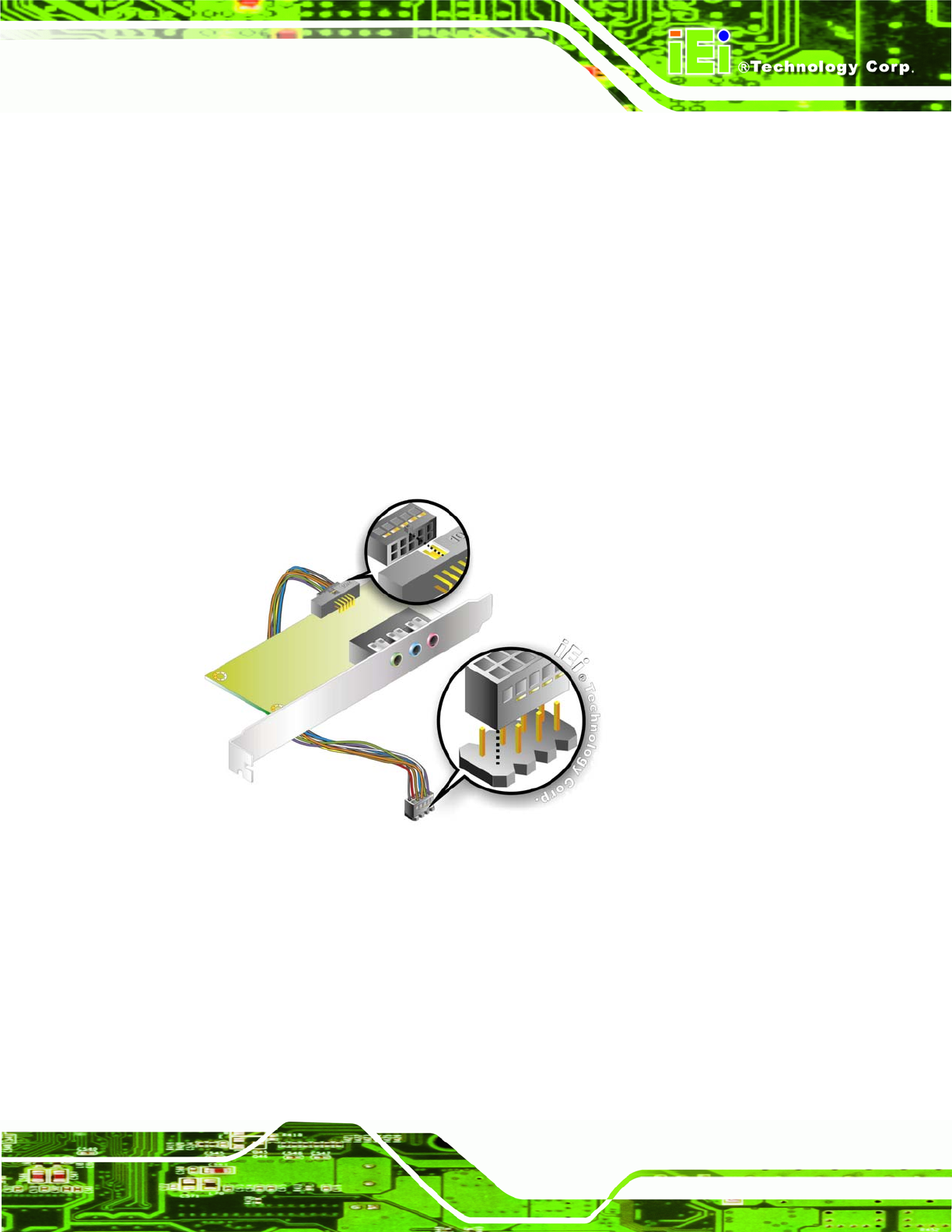
4.8.1 5.1 Channel Audio Kit Installation
The audio kit attaches to the audio connector. The audio kit provides 5.1 channel audio.
To install the audio kit, please refer to the steps below:
Step 1: Connect the cable to the audio kit. Connect the in cluded cable to the audio kit.
Make sure pin 1 align s with the marked pin.
Step 2: Conect the cable to the board. Conne ct the other end of the cable to the board.
Make sure to line up the marked pin 1.
Figure 4-9: 5.1 Channel Audio Kit
Step 3: Mount the audio kit onto the chassis. Once the audio kit is connected to the
board, secure the audio kit bracket to the system chassis.
Step 4: Connect the audio devices. Connect speakers and external audio sources to
the audio jacks on the audio kit.
Step 5: Install the driver. Install the 5.1 channel audio driver included with the board.
Step 0: