
User Manual
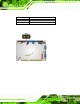
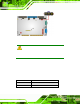


Table Of Contents
- 1 Introduction
- 2 Unpacking
- 3 Connectors
- 3.1 Peripheral Interface Connectors
- 3.2 Internal Peripheral Connectors
- 3.2.1 ATX Power Enable Connector
- 3.2.2 Audio Connector (10-pin)
- 3.2.3 Backlight Inverter Connector
- 3.2.4 Battery Connector
- 3.2.5 CompactFlash® Socket
- 3.2.6 Digital Input/Output (DIO) Connector
- 3.2.7 Fan Connector (+5V)
- 3.2.8 Floppy Disk Connector
- 3.2.9 Front Panel Connector (8-pin)
- 3.2.10 IDE Connector (40-pin)
- 3.2.11 Infrared Interface Connector (5-pin)
- 3.2.12 Keyboard/Mouse Connector
- 3.2.13 Parallel Port Connector
- 3.2.14 Power Connector
- 3.2.15 SATA Drive Connectors (Optional)
- 3.2.16 Serial Port Connector (RS-232/422/485)
- 3.2.17 TTL Connector
- 3.2.18 Internal USB Connectors
- 3.2.19 -VCC Power Connector
- 3.3 External Peripheral Interface Connectors
- 4 Installation
- 5 BIOS Screens
- A BIOS Menu Options
- B One Key Recovery
- C Terminology
- D Watchdog Timer
- E Hazardous Materials Disclosure
IOWA-LX-600 Half-size CPU Card
Page 52
4.7 Chassis Installation
4.7.1 Airflow
WARNING:
Airflow is critical to the cooling of the CPU and other onboard
components. The chassis in which the IOWA-LX-600 must have air
vents to allow cool air to move into the system and hot air to move out.
The IOWA-LX-600 must be installed in a chassis with ventilation holes on the sides
allowing airflow to travel through the heat sink surface. In a system with an individual
power supply unit, the cooling fan of a power supply can also help generate airflow
through the board surface.
4.7.2 Backplane Installation
Before the IOWA-LX-600 can be installed into the chassis, a backplane must first be
installed. Please refer to the installation instructions that came with the backplane and the
chassis to see how to install the backpl ane into the chassis.
NOTE:
IEI has a wide range of backplanes available. Please conta ct a vendor,
reseller or an IEI sales representative at
2sales@iei.com.tw or visit the
IEI website (
2http://www.ieiworld.com.tw) to find out more about the
available chassis.
4.7.3 CPU Card Inst allation
To install the CPU card onto the backplane, carefully align the CPU card edge connector
with the CPU card socket on the backplane. To do this, please refer to the reference
material that came with the backplane. Next, secure the CPU card to the chassis. To do
this, please refer to the reference material that came with the chassis.