
User Manual
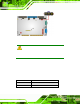
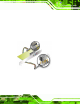


Table Of Contents
- 1 Introduction
- 2 Unpacking
- 3 Connectors
- 3.1 Peripheral Interface Connectors
- 3.2 Internal Peripheral Connectors
- 3.2.1 ATX Power Enable Connector
- 3.2.2 Audio Connector (10-pin)
- 3.2.3 Backlight Inverter Connector
- 3.2.4 Battery Connector
- 3.2.5 CompactFlash® Socket
- 3.2.6 Digital Input/Output (DIO) Connector
- 3.2.7 Fan Connector (+5V)
- 3.2.8 Floppy Disk Connector
- 3.2.9 Front Panel Connector (8-pin)
- 3.2.10 IDE Connector (40-pin)
- 3.2.11 Infrared Interface Connector (5-pin)
- 3.2.12 Keyboard/Mouse Connector
- 3.2.13 Parallel Port Connector
- 3.2.14 Power Connector
- 3.2.15 SATA Drive Connectors (Optional)
- 3.2.16 Serial Port Connector (RS-232/422/485)
- 3.2.17 TTL Connector
- 3.2.18 Internal USB Connectors
- 3.2.19 -VCC Power Connector
- 3.3 External Peripheral Interface Connectors
- 4 Installation
- 5 BIOS Screens
- A BIOS Menu Options
- B One Key Recovery
- C Terminology
- D Watchdog Timer
- E Hazardous Materials Disclosure
IOWA-LX-600 Half-size CPU Card
Page 47
4.6 Jumper Settings
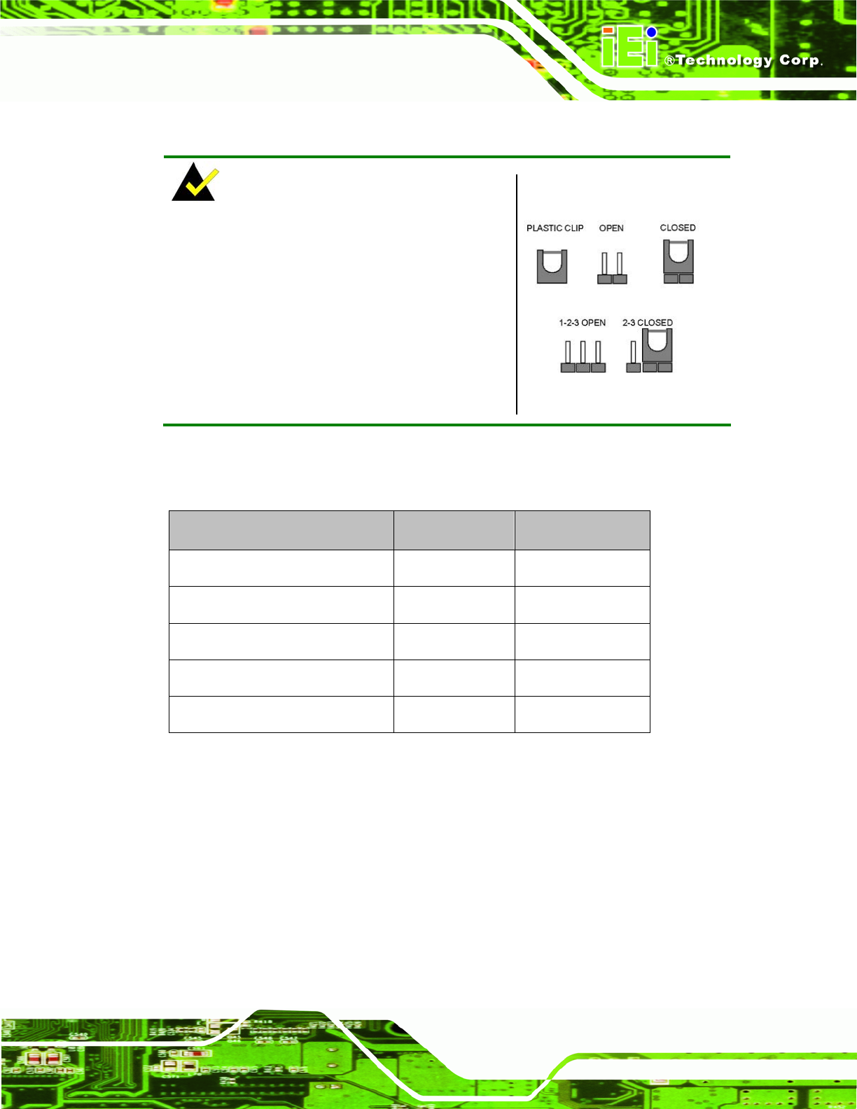
NOTE:
A jumper is a metal bridge used to close an
electrical circuit. It consists of two or three metal
pins and a small metal clip (often protected by a
plastic cover) that slides over the pins to connect
them. To CLOSE/SHORT a jumper means
connecting the pins of the jumper with the plastic
clip and to OPEN a jumper means removing the
plastic clip from a jumper.
Figure 4-3: Jumper Locations
Before the IOWA-LX-600 is install ed in the system, the jumpe rs must be set in ac cordance
with the desired configuration. The jumpers on the IO WA-LX-600 are listed in
66Table 4-1.
Description Type Label
AT/ATX power mode setting 2-pin h eader JP2
CompactFla sh® card setup 3-pin header JP7
COM3 RS-422/485 select 3-pin header JP3
LCD voltage sele ct 3-pin header JP5
LCD TTL clock select 3-pin header JP6
Table 4-1: Jumpers
4.6.1 AT/ATX Power Select
Jumper Label:
JP2
Jumper Type:
2-pin header
Jumper Settings:
See
6Table 4-2
Jumper Location:
See
6Figure 4-4