
User Manual
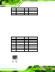
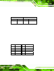
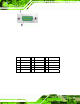


Table Of Contents
- 1 Introduction
- 2 Unpacking
- 3 Connectors
- 3.1 Peripheral Interface Connectors
- 3.2 Internal Peripheral Connectors
- 3.2.1 ATX Power Enable Connector
- 3.2.2 Audio Connector (10-pin)
- 3.2.3 Backlight Inverter Connector
- 3.2.4 Battery Connector
- 3.2.5 CompactFlash® Socket
- 3.2.6 Digital Input/Output (DIO) Connector
- 3.2.7 Fan Connector (+5V)
- 3.2.8 Floppy Disk Connector
- 3.2.9 Front Panel Connector (8-pin)
- 3.2.10 IDE Connector (40-pin)
- 3.2.11 Infrared Interface Connector (5-pin)
- 3.2.12 Keyboard/Mouse Connector
- 3.2.13 Parallel Port Connector
- 3.2.14 Power Connector
- 3.2.15 SATA Drive Connectors (Optional)
- 3.2.16 Serial Port Connector (RS-232/422/485)
- 3.2.17 TTL Connector
- 3.2.18 Internal USB Connectors
- 3.2.19 -VCC Power Connector
- 3.3 External Peripheral Interface Connectors
- 4 Installation
- 5 BIOS Screens
- A BIOS Menu Options
- B One Key Recovery
- C Terminology
- D Watchdog Timer
- E Hazardous Materials Disclosure
IOWA-LX-600 Half-size CPU Card
Page 38
PIN DESCRIPTION PIN DESCRIPTION
1 KEYBBOARD DATA 2 MOUSE DATA
3 GND 4 GND
5 KEYBOARD CLOCK
6 MOUSE CLOCK
Table 3-22: PS/2 Connector Pinouts
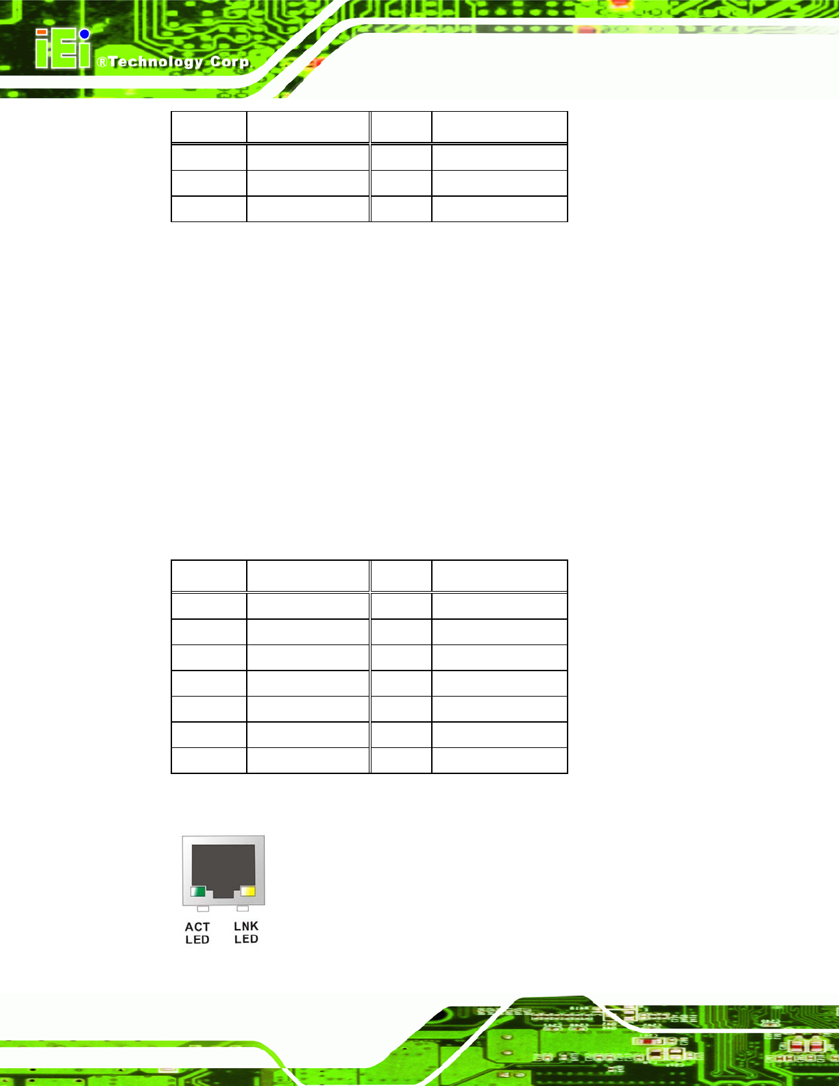
3.3.2 RJ-45 Ethernet Connector
CN Label:
CN22
CN Type:
RJ-45
CN Location:
See
6Figure 3-21
CN Pinouts:
See
6Table 3-23
The RJ-45 Ethernet connector on the IOWA-LX-600 provides connectivity to a 10/100
megabit Ethernet connection between t he IOWA-LX-600 and a Local Area Network (LAN)
through a network hub.
PIN DESCRIPTION PIN DESCRIPTION
1 TX+ 8 N/C
2 GROUND 9 ACT_LED-
3 TX- 10 ACT_LED+
4 RX+ 11 LINK_LED -
5 GROUNG 12 LINK_LED+
6 RX- 13 GROUND
7 N/C 14 GROUND
Table 3-23: RJ-45 Ethernet Connector Pinouts